In the world of network engineering, learning a new syntax for a NOS can be daunting if you need a specific config quickly. Juniper is a popular option for service providers/data centers and is widely deployed across the world.
This is a continuation of the Rosetta stone for network operating systems series. In this article we will be covering multi-protocol label switching (MPLS) using label distribution protocol (LDP). We are sticking with LDP as MikroTik does not have wide support for RSVP-TE.
You can find the first two articles of the series here:
While many commands have almost the exact same information, others are as close as possible. Since there isn’t always an exact match, sometimes you may have to run two or three commands to get the information needed.
Using EVE-NG for testing
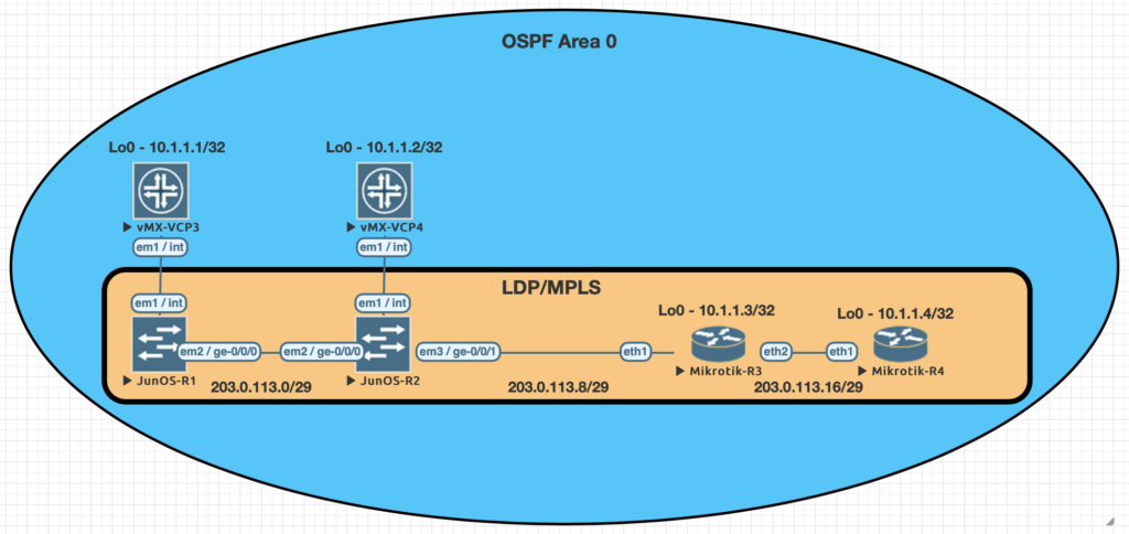
We conducted utilized EVE-NG for all of the testing with the topology seen below.
Juniper Command
MikroTik Command
show ldp neighbor
mpls ldp neighbor print
show ldp interface
mpls ldp interface print
show route forwarding-table family mpls
mpls forwarding-table print
show ldp database
mpls remote-bindings print
show ldp database
mpls local-bindings print
show mpls label usage
mpls print
set interfaces ge-0/0/0 unit 0 family mpls
set protocols ldp interface ge-0/0/0.0
/mpls ldp interface
add interface=ether1
set routing-options router-id 10.1.1.1
/mpls ldp
set enabled=yes lsr-id=10.1.1.3
Examples of the commands above
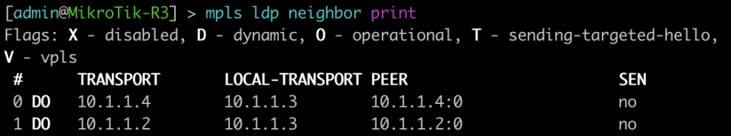
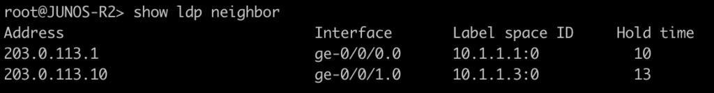
This first command will show you some basic information about your MPLS LDP neighbors. On juniper you can add the keyword detail to the end for additional information on the neighbors.
[admin@MikroTik-R3] > mpls ldp neighbor print
root@JUNOS-R2> show ldp neighbor
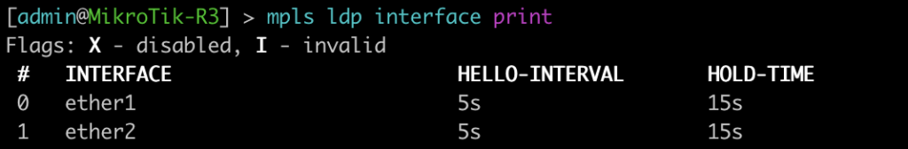
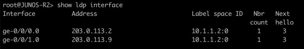
This command will list all of the interfaces that are currently enabled for LDP.
[admin@MikroTik-R3] > mpls ldp interface print
root@JUNOS-R2> show ldp interface
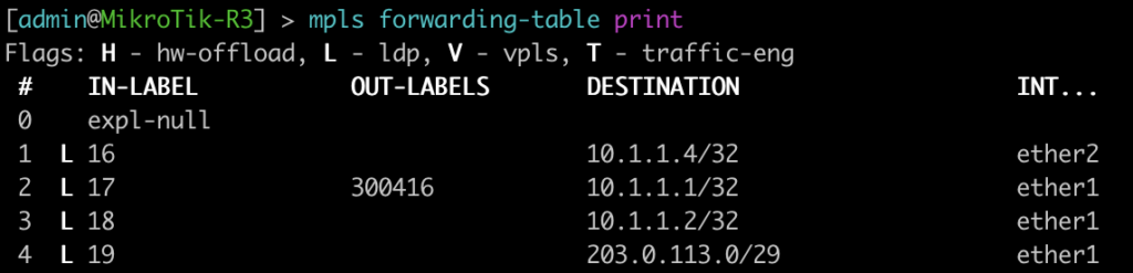
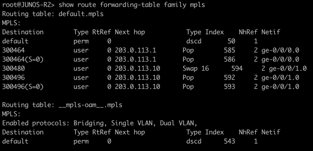
Use this command to display the MPLS forwarding table which shows what labels are assigned, the interface used and the next-hop. It will also tell you the action taken such as pop, swap, or push.
[admin@MikroTik-R3] > mpls forwarding-table print
root@JUNOS-R2> show route forwarding-table family mpls
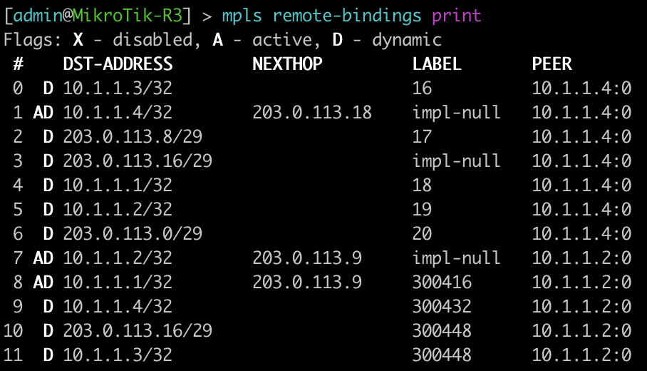
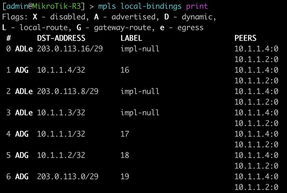
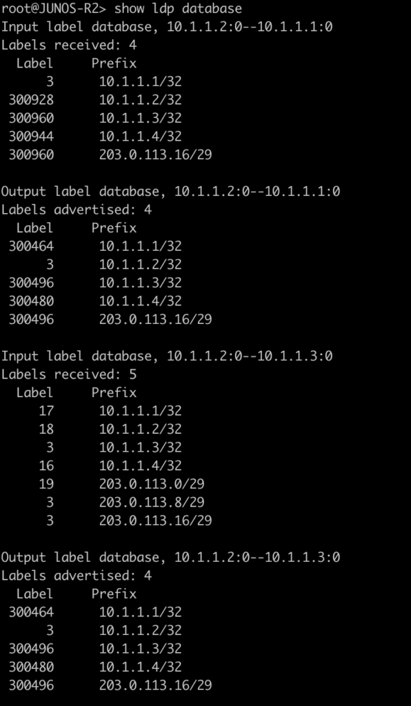
The next two commands will be combined since juniper only has one command to be equivalent to mikrotiks output. This is will show the advertised and received labels for all of the prefixes known to LDP as well as the label associated with it and where it was learned from. On JunOS you will notice label 3. This is juiper’s method to signal implicit null and request label popping by the downstream router.
[admin@MikroTik-R3] > mpls remote-bindings print
[admin@MikroTik-R3] > mpls local-bindings print
root@JUNOS-R2> show ldp database
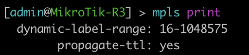
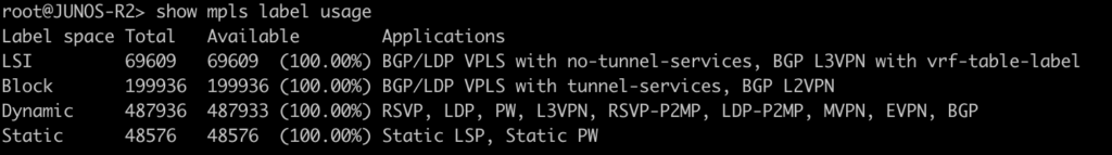
This last command will show the label ranges and what they are used for.
[admin@MikroTik-R3] > mpls print
root@JUNOS-R2> show mpls label usage
Configurations
root@JUNOS-R1# show | display set
set version 18.2R1.9
set system root-authentication encrypted-password "$6$iCt/DOMc$lQFrIQdrjot1m0lIY5A2eUaOmat87oAqbNZWd/3KPij2QWTlBQEyYlVbb1/emd2N9VKN6NL0olk.kJK7mLcgM0"
set system host-name JUNOS-R1
set system syslog user * any emergency
set system syslog file messages any notice
set system syslog file messages authorization info
set system syslog file interactive-commands interactive-commands any
set system processes dhcp-service traceoptions file dhcp_logfile
set system processes dhcp-service traceoptions file size 10m
set system processes dhcp-service traceoptions level all
set system processes dhcp-service traceoptions flag packet
set interfaces ge-0/0/0 unit 0 family inet address 203.0.113.1/29
set interfaces ge-0/0/0 unit 0 family mpls
set interfaces fxp0 unit 0 family inet dhcp vendor-id Juniper-vmx-VM6015C6C2F2
set interfaces lo0 unit 0 family inet address 10.1.1.1/32
set routing-options router-id 10.1.1.1
set protocols ospf area 0.0.0.0 interface ge-0/0/0.0
set protocols ospf area 0.0.0.0 interface lo0.0 passive
set protocols ldp interface ge-0/0/0.0
root@JUNOS-R2# show | display set
set version 18.2R1.9
set system root-authentication encrypted-password "$6$x.MmgodX$XG1D3lCYPC8VpIhE8NXxdRJaoZS8sYB2PB0v50POrrx6Mi.nhnTB/41NGFk1zL8RDQBdR/lCPG2NazFDYgzNf/"
set system host-name JUNOS-R2
set system syslog user * any emergency
set system syslog file messages any notice
set system syslog file messages authorization info
set system syslog file interactive-commands interactive-commands any
set system processes dhcp-service traceoptions file dhcp_logfile
set system processes dhcp-service traceoptions file size 10m
set system processes dhcp-service traceoptions level all
set system processes dhcp-service traceoptions flag packet
set interfaces ge-0/0/0 unit 0 family inet address 203.0.113.2/29
set interfaces ge-0/0/0 unit 0 family mpls
set interfaces ge-0/0/1 unit 0 family inet address 203.0.113.9/29
set interfaces ge-0/0/1 unit 0 family mpls
set interfaces fxp0 unit 0 family inet dhcp vendor-id Juniper-vmx-VM6015C6C3B3
set interfaces lo0 unit 0 family inet address 10.1.1.2/32
set routing-options router-id 10.1.1.2
set protocols ospf area 0.0.0.0 interface ge-0/0/0.0
set protocols ospf area 0.0.0.0 interface ge-0/0/1.0
set protocols ospf area 0.0.0.0 interface lo0.0 passive
set protocols ldp interface ge-0/0/0.0
set protocols ldp interface ge-0/0/1.0
Understanding the choices – why is routing design so important?
Routing is the foundation of every IP network. Even a router as small as the one in your home has a routing table and makes routing decisions.
Selecting a routing architecture is a critical but often overlooked step to ensure that a startup WISP can provide the necessary performance, scalability and resiliency to its subscribers.
This post will go through each the major design types and highlight pros/cons and when it is appropriate to use a particular routing architecture.
A note on IPv6
Dual stack is assumed in all of the designs presented. The cost of IPv4 public will continue to climb.
It’s no longer a scalable option in 2020 to build an ISP network without at least a plan for IPv6 and ideally a production implementation.
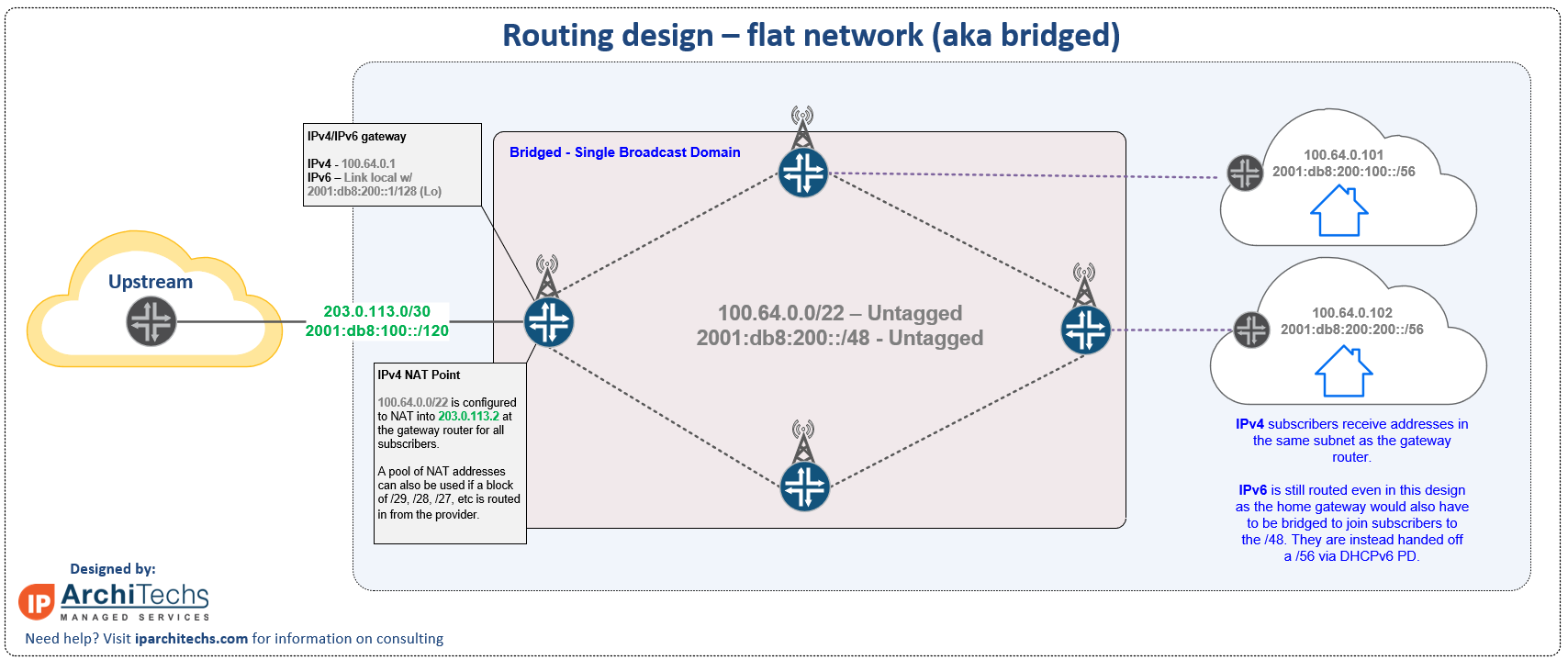
1. Flat network (aka bridged network)
“Behind the L3 boundary, there be L2 dragons”
-ancient network proverb
Unfortunately, this is often the worst choice for all but the smallest WISPs that don’t have any plans to scale beyond 1 to 100 subscribers.
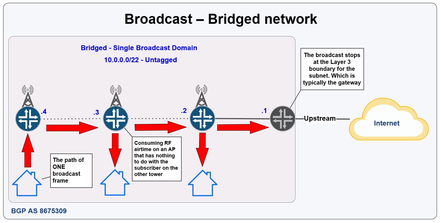
Bridged networks with one or more subnets in the same L2 broadcast domain are the most commonly deployed routing design that we see in day to day consulting working for WISPs.
Bridged networks are attractive because they require minimal networking knowledge to get up and running.
These networks have a number of limitations in scale and performance and are susceptible to loops. They also can cause RF problems with the number of broadcasts sent across all towers.
This drawing is from the blog post ‘ WISP Design – Migrating from Bridged to Routed’ and has more information on issues with bridged networks and how to migrate a current bridged network to routed.
This is not an ideal choice for a startup, because it almost guarantees you’ll need a disruptive, time consuming and expensive migration once the subscriber count starts to grow.
CAUTION: “for-profit” WISPs – it is **NOT**recommended to deploy this design.
When should I deploy this network type?
Now that the “Most of you probably shouldn’t do this” warnings are out of the way… there are a few corner cases of WISPs that are for government use, non-profits, research, etc that this design can be a good fit for.
Use this design when:
simplicity is the ultimate goal (way beyond all others)
the WISP will *never* go beyond 100 subscribers
the WISP will be managed by someone without a networking and/or technical background
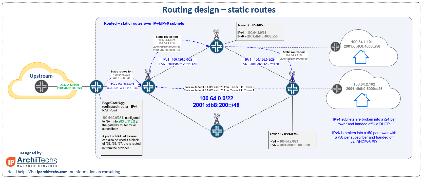
Static routing is a *slight* step up from a bridged network.
With layer 3 separation between the towers, the risks of major performance issues with growth go way down.
However, the administrative burden of growth is still an issue with static routes.
This design can be used for a very simple network with only a few routers until a dynamic routing protocol can be configured.
When **NOT** to deploy this design
Startup WISPs that plan on having more than one geographic IP transit location should consider one of the two BGP based designs as there are better policy options to influence routing.
Startup WISPs that expect rapid growth will not want to use this design, it doesn’t scale well and is difficult to manage for more than a few routers. (< 5 routers)
WISPs that want to dynamically failover between backhaul links can quickly get into issues when trying to manage failover for more than one or two routers with static routes.
If traffic engineering is desired, this is not the right design
Note: Static routing in this context means static routes for all subnet reachability – it is not meant to include a static route (when needed) to 0.0.0.0/0 as a default on an isolated management network or for a DIA circuit
When should you deploy this design?
A small network that will never exceed 1 to 5 routers
An extremely lossy and/or high-latency RF network that will cause issues with dynamic protocols.
If knowledge of OSPF/BGP becomes a roadblock in getting a routed network up and running
If routing is a knowledge gap, use this in the first 30 to 60 days to test radios and Internet access while working on dynamic routing. Don’t leave a network that is intended to scale on static routes.
Do I really need dynamic routing for a WISP that’s very small?
The answer lies in the drawing above…
it’s easy to see when looking at this drawing how complex and cumbersome static routing can become even for just 2 to 3 routers.
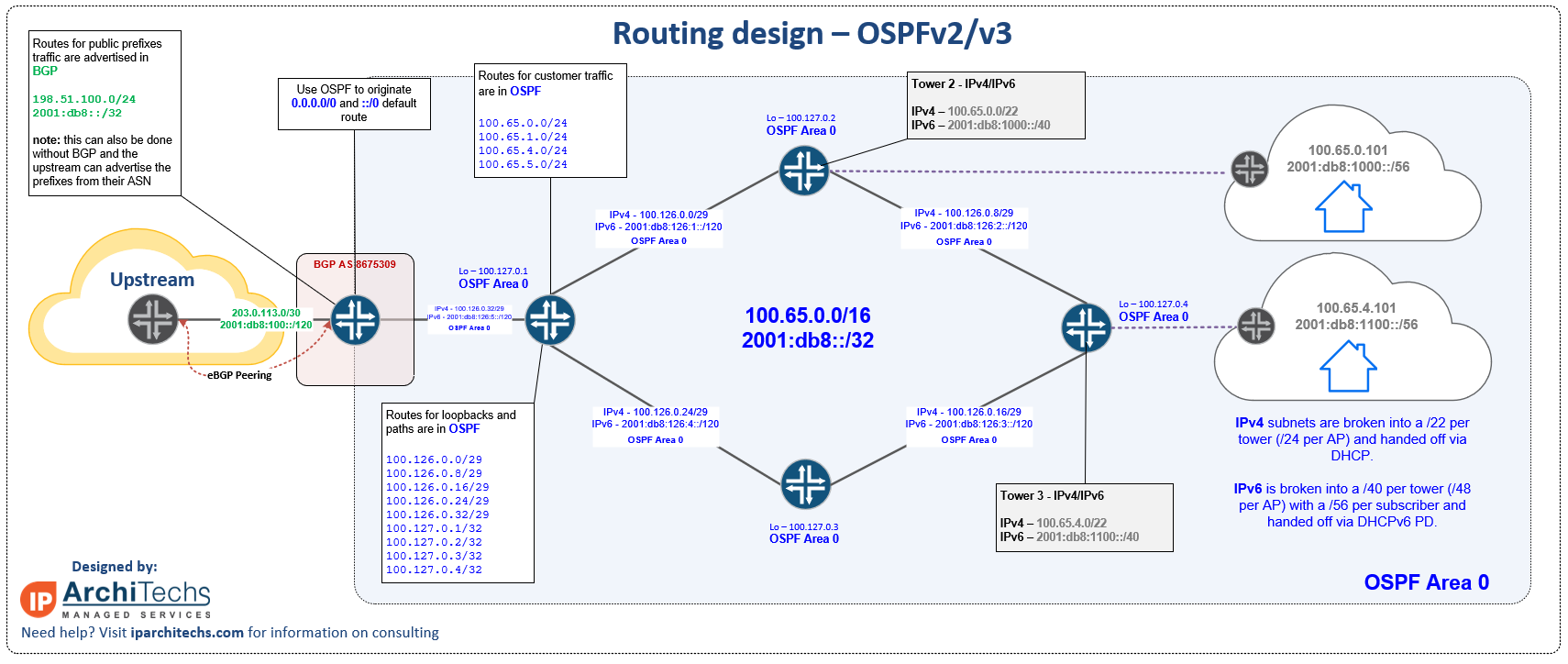
Dynamic routing using OSPF
Open Shortest Path First or OSPF is an interior gateway protocol defined by RFC2328 for version 2 (IPv4) and RFC5340 for version 3 (IPv6).
Without going into an enormous amount of detail about the background of OSPF and IGPs in general (RIP, EIGRP, IS-IS), which is out of the scope of this post, here are a few key points about the protocol:
Relies on ‘cost‘ which is an arbitrary value that can be set to mirror the speed of a given RF link (typically under ideal conditions) if desired to better reflect the “best” path through a series of backhauls.
A link-state protocol – this means that OSPF is concerned with the speed, topology and current state of every link on every router within an area. Due to this behavior, flapping RF links can sometimes case a “ripple” effect of bouncing routes across an area. This is one good use case to put non-core routes at towers into separate areas. (alternatively if BGP is used, only transit/loopback routes remain in OSPF so the net effect is similar)
OSPF does a great job at mapping out paths, speeds and reachability for subnets , this is why it’s often the first dynamic routing protocol many WISPs first learn. It also has significant limitations when used as a protocol for policy, which BGP is better suited for – the next design will show them paired together to get the best mix of reachability/paths + policy.
When **NOT** to deploy this design
Startup WISPs that plan on having more than one geographic IP transit location should consider one of the two BGP based designs as there are better policy options to influence both default and tower routing.
A WISP that plans to offer private L2VPN/L3VPN services should use the iBGP/OSPF/MPLS design in the next section.
A WISP that has or will have a complex tower topology with many redundant paths and needs a heavy focus on traffic engineering should consider the eBGP design in the last section.
When should you deploy this design?
A WISP that has no plans to offer private L2VPN/L3VPN services can successfully use this design
A WISP that will have mostly a non-mesh or significant partial-mesh physical topology of towers and backhauls – essentially this means that policy will likely not be required for traffic engineering and redundant RF PTP links can exist in standby and not be used towards aggregate capacity.
If the amount of IPv4 space used by a startup WISP will be less than a /24, then MPLS/VPLS is not required to improve IPv4 subnetting efficiency. While it is possible to deploy MPLS with only OSPF, the next section on iBGP will recommend the deployment of MPLS/LDP with iBGP/OSPF.
Border Gateway Protocol or BGP is an exterior gateway protocol defined by RFC4271 for IPv4 and RFC2545 for IPv6. Although BGP started out as a protocol that was intended only for use on the Internet between public ASNs, it quickly became used in a variety of network types due to the policy options it offers. Policy describes BGP in a nutshell, it isn’t concerned with link speeds, physical topology or link state…BGP is purely focused on policy and the best path algorithm.
Multiprotocol Label Switching or MPLS is a forwarding protocol that assigns labels to routes and allows for the abstraction of different services carried in an overlay on top of the routed/label-switched core. MPLS is defined in RFC3031.
Similar to OSPF, I won’t go into an enormous amount of detail about BGP and MPLS, which is out of the scope of this post, but here are a few key points about each protocol:
BGP overview for WISPs
BGP uses TCP port 179 to exchange routing information with another BGP speaker.
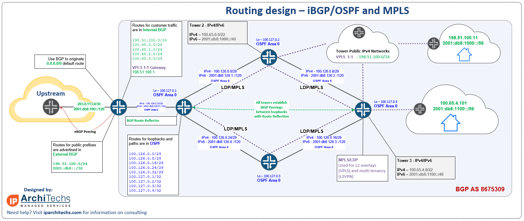
Internal BGP vs. External BGP has little to do with whether it’s used on the Internet. It simply means either a peering within the same ASN (internal) or a peering between different ASNs (external). There are a number of differences between the two, but the most fundamental is the next hop behavior – eBGP rewrites the next hop to be the local router before advertising the route whereas iBGP does not change the next hop by default.
Internal BGP uses recursive routing (next hop is not directly connected and requires route lookup) and does not change its next hop. OSPF is used to advertise the next hop so the next hop (typically a loopback) is always reachable. If you reference the drawing for this design section, you’ll notice the routes are either green (BGP) or blue (OSPF) to help clarify how they work together
Internal BGP relies on route reflectors (RR) to manage all routes in an ASN. This helps to avoid a full mesh of peerings. Normally a router in the core will act as the route reflector. One of the advantages for a WISP of using RRs is simplified tower router configs – they will always peer to the same pair of RRs regardless of location.
Using BGP in a WISP allows for a number of policy options to make selection of a default route or influencing a tower path much easier.
One of the greatest benefits of using BGP in a WISP is the simplification of routing protocols for host and subscriber subnets. Once routing is BGP end to end from the peering to the upstream router all the way to the last mile at the tower, it becomes easier to manage and apply policy.
BGP also offers better scaling options to grow than OSPF on a WISP network. I’ve consulted for a number of WISPs over 10,000 subscribers (which is a fairly sizeable WISP) and the vast majority of them run BGP due to policy and scale limitations of OSPF.
MPLS Overview for WISPs
MPLS requires a signaling protocol to exchange labels. Label Distribution Protocol or LDP is most commonly used. LDP uses TCP port 646 to build sessions and UDP port 646 for discovery. LDP is what takes the route information from other protocols like OSPF and BGP and assigns labels to it for forwarding.
MPLS is an incredibly useful tool for WISPs because it allows for the network to be sliced into virtual segments at layer 2 (L2VPN) or layer 3 (L3VPN) to deliver services that subscribers may ask for, or for internal needs like isolated management routing tables or VRFs (Virtual Routing and Forwarding).
One of the most helpful features of MPLS for a WISP lately has been the use of VPLS (L2VPN) to make subnetting a public IPv4 block more efficient. Traditionally, WISPs would try and break up a public block into small subnets to have public IPv4 available at every tower. As IPv4 became more scarce and costly, this became much harder to do. VPLS solves this problem by hosting the subnet at a data center or central point and then extending Layer 2 to wherever it is needed. This service is highlighted in purple in the drawing
BGP – More information
Network Collective EPISODE 17 – BGP: PEERING AND REACHABILITY
MPLS – More information MikroTik US MUM 2016 – Dallas, Texas
MPLS Overview, Design and Implementation for WISPs
When **NOT** to deploy this design
If a WISP feels this is more complex than they can handle, the previous OSPF design can be used with loopbacks to prepare for the addition of BGP and MPLS at a future date. While it will require some migration time, it still provides a path forward to enable more advanced services.
If your focus is mainly residential, your subscriber count will never exceed 1000 subscribers and your tower topology is relatively simple, then you can likely use the previous OSPF design successfully.
If Traffic Engineering without using segment routing or MPLS TE is the single most important design requirement, then the eBGP design in the next section is the best choice.
When should you deploy this design?
All the time! (almost…) This is probably the most common type of design we build and deploy as WISP consultants because it:
Scales well (we’ve deployed at the scale of thousands of towers)
Is easier to manage operationally – using route reflectors centralizes routing policy decisions.
Has the most options available to deliver overlay services which align with the ability of the business to rapidly bring a product to market.
Isn’t new – this marriage of BGP/OSPF/MPLS has been the foundation of most Telco and Fiber operators for more than a decade. The reason is simple – it works.
Deploying L3VPN services for management VRF or for business customers
Planning a hybrid build with fiber and will be moving to equipment that supports more advanced features like MPLS TE with Fast Reroute or Segment Routing (even if you can’t leverage all traffic engineering features day one – the design will be ready to grow into more capable gear)
One of the questions we are often asked about this design is:
Should I start with all of these protocols from the very beginning. Why not just pick BGP or OSPF? Why do I need both?
The answer is twofold
It’s far easier to learn more advanced routing concepts when the network is smaller or a complete greenfield. At some point you’ll need more advanced tools and migrating 25, 50 or 100+ towers is expensive, disruptive and incredibly time consuming.
The reason you wouldn’t pick one or the other in this design is that each protocol focuses on its strengths – OSPF is excellent for path calculation and topology and BGP is excellent at policy. With BGP working on top of OSPF, you get the best of both worlds.
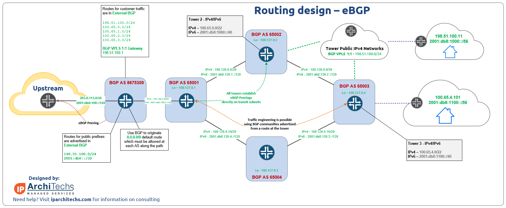
Dynamic routing using eBGP
This is definitely one of the newest designs we’ve worked with and deployed into production. It’s growing in popularity because using BGP for all routing actually simplifies the design quite a bit while still being able to deliver VPLS services. This design also allows for incredibly diverse traffic engineering options and full IPv4/IPv6 dual stack with BGP which is limited in some vendors.
Vendor note: It’s worth noting that some of the limitations in the current version of MikroTik RouterOS 6.xx are what prompted this specific design
MPLS Traffic engineering has significant limitations and cannot enforce more than one policy between two points. It also cannot enforce policy across OSPF areas
Dual stack with iBGP in IPv6 will not be functional until Router OS Version 7 is in prof and out of beta.
Rather than list bullet points on this topic to illustrate why and how eBGP is useful for traffic engineering in WISPs, i’ll share the following video from:
MikroTik US MUM 2017 – Denver, Colorado
When **NOT** to deploy this design
If a WISP requires L3VPN and/or VRFs for management, then the previous iBGP design would be better suited for that
If BGP knowledge becomes a roadblock that cannot be settled or worked around, then moving back to an OSPF only design is an option (However, I always recommend using labs like GNS3 or EVE-NG to train engineers and techs to solve this problem)
When should you deploy this design?
When traffic engineering is the primary driver for the business, but utilizing equipment that supports segment routing/MPLS TE is out of the budget, this is a workable solution to have total control of traffic paths.
BGP Communities can be used to steer a subnet along any path desired
Traffic paths can be modified using communities for both traffic to and from the towers.
When IPv6 dual stack with BGP on the tower network is required (Again a limitation specifically attributed to MikroTik RouterOS v6 and fixed in v7 beta)
Even with the shallow depth i’ve given the routing protocols, this should still highlight the pros and cons of each design and also illustrate the role of the network vendor in supporting the necessary protocols.
Take some time (even if you have to read this article in several passes) to really understand the business case of your WISP, what you sell and what’s important for you to develop in the future.
Then evaluate the protocols needed vs. the budget required for more advanced equipment and calculate the ROI of features and agility vs. equipment/licensing cost.