When MikroTik announced the CRS3xx series switches a few years ago, one of the most exciting aspects of that news release was the prospect of L3 forwarding in hardware on very inexpensive devices.
A quick review of the Marvell Prestera ASIC family showed a number of advanced routing, switching, MPLS and VxLAN capabilites.
Fast forward to 2020, where MikroTik has started to enable some of those features in RouterOS v7 beta.
Now we can finally take some of the CRS3xx switches and test their capabilities with L3 forwarding performance in hardware
CRS 3xx series capabilities overview
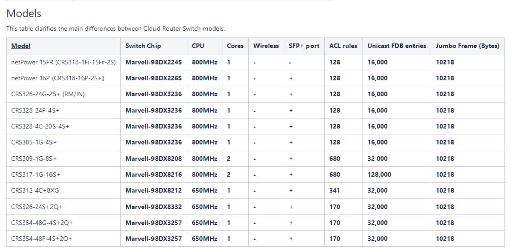
Before getting into the testing, it’s probably helpful to review some of the basic specs and capabilities of the CRS3xx switch line.
Here is a chart from MikroTik that outlines ACL rule count, Unicast FDB entries and MTU size.
CRS 3xx model comparison
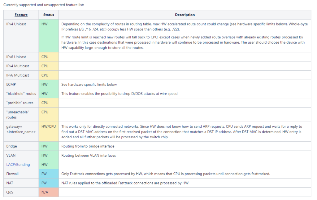
MIkroTik has been working on the development of the features listed below to offload into hardware.
For the tests in this article, we’ll be using IPv4 Unicast and Inter-VLAN routing.
Supported feature list
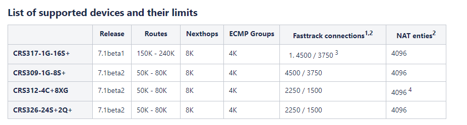
Currently, the following switches are supported.
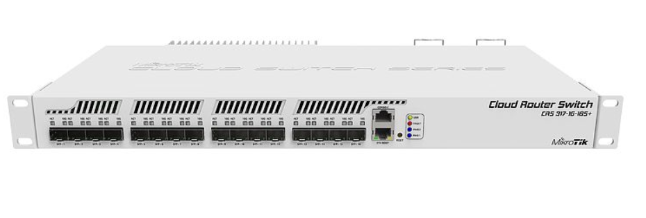
For the testing in this article, we are using the CRS317-1G-16S+
Switches supported by 7.1beta2
Performance testing – overview
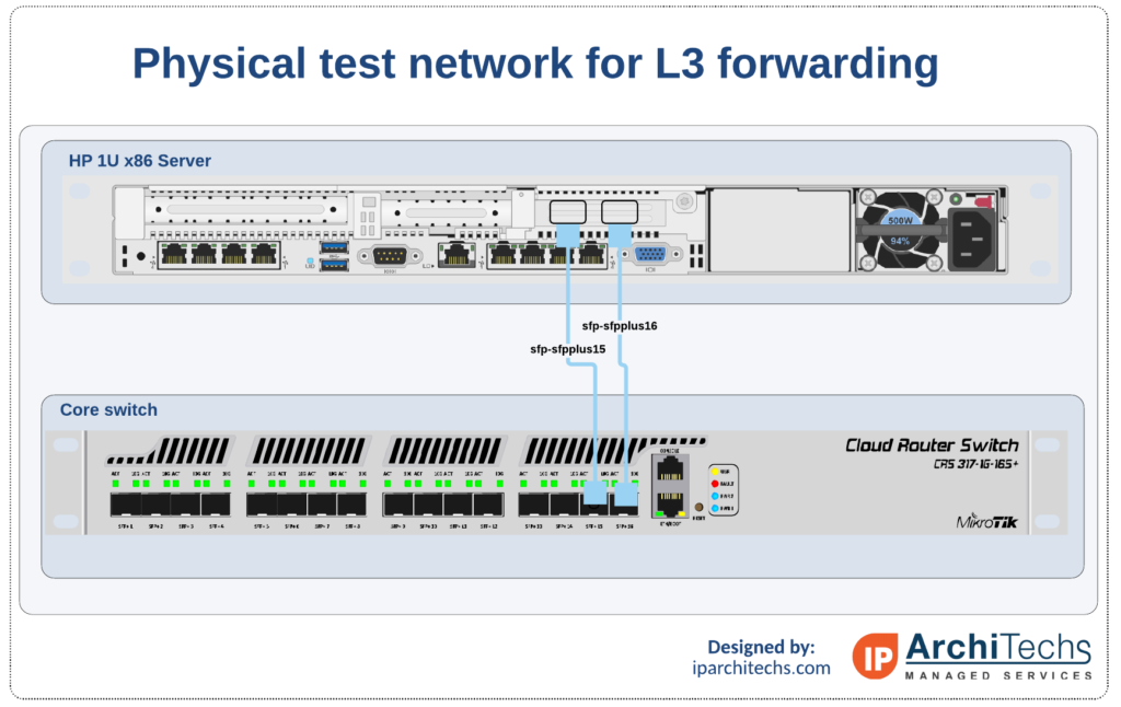
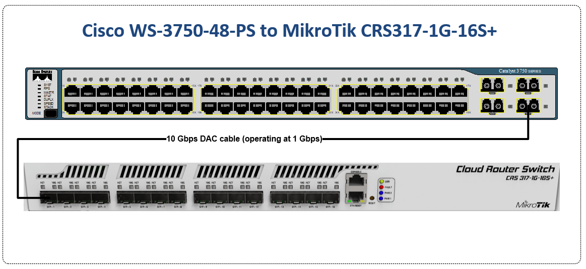
The physical setup for testing is fairly straightforward.
HP DL380 gen7 with ProxMox PVE 6.2-4
2 x 10G Multimode OM4 fiber jumpers
4 x 10G Multimode SFPs
CRS 317-1G-16S+ running RouterOS 7.1beta2
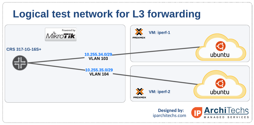
The logical setup is also very straightforward
ProxMox/KVM hypervisor using PVE 6.2-4
Two RFC1918 subnets and VLANs to test intervlan routing performance
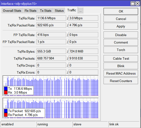
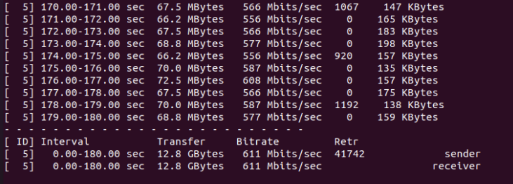
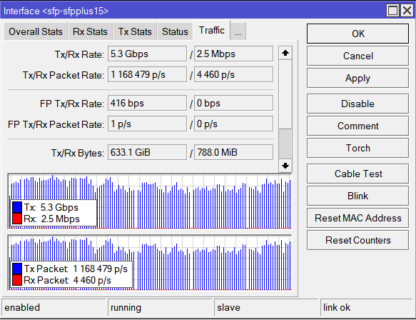
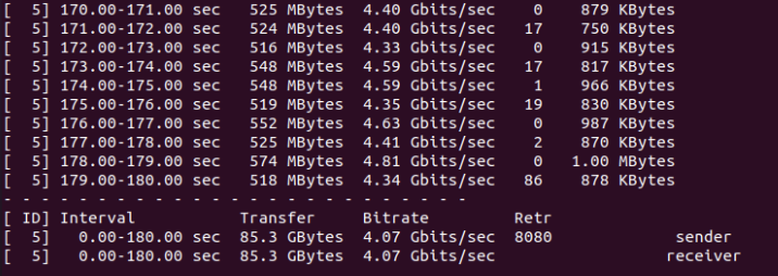
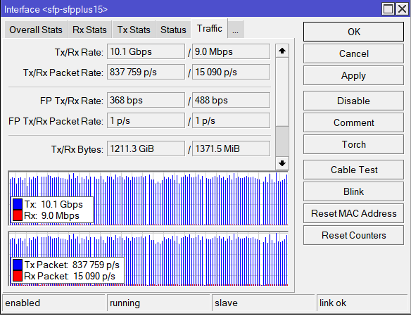
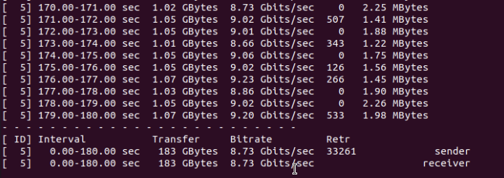
The initial results are very promising. Getting close to 10G sustained L3 throughput using an ASIC on a device that lists for $399 USD is unheard of.
The most noteworthy items for improvement are the number of TCP retransmits in the iperf testing and the speed reduction as the MTU is reduced.
Normally, most ASIC based platforms will push 96 bytes through as fast as 1500 bytes. The retransmits suggest that more work is needed in the way RouterOS interfaces with the switching buffers for L3 HW offload
This is also on a beta version of RouterOS that will still go through many revisions before going into prod so I would expect to see the performance to improve as the code matures.
All things considered though, things are looking great to take the CRS3xx series and be able to deploy them as a true L3 switch in prod sometime in 2021.
One of the most difficult configuration challenges for MikroTik equipment seems to be switching and VLANs in the CRS series. Admittedly, the revamp of VLAN configuration for MikroTik CRS switches in early 2018 made things a lot easier. But, sometimes there is still confusion on how to configure VLANs and IP addresses in VLANs with MikroTik RouterOS operating on a switch.
This will only cover VLAN configuration for CRS 3xx series switches in RouterOS as SwitchOS is not nearly as common in operational deployments.
CRS 1xx/2xx series use an older style of configuration and seem to be on the way out so I’m not 100% sure whether or not i’ll write a similar guide on that series.
If you’ve been in networking for a while, you probably started with learning the Cisco CLI. Therefore, it is helpful to compare the commands if you want to implement a network with a MikroTik and Cisco switches.
This is the fourth post in a series that creates a Rosetta stone between IOS and RouterOS. Here are some of the others:
Click here for the first article in this series – “Cisco to MikroTik BGP command translation” Click here for the second article in this series – “Cisco to MikroTik OSPF command translation” Click here for the third article in the series – “Cisco to MikroTik MPLS command translation”
While many commands have almost the exact same information, others are as close as possible. Since there isn’t always an exact match, sometimes you may have to run two or three commands to get the information needed.
Hardware for testing
In the last article, we began using EVE-NG instead of GNS3 to emulate both Cisco IOS and RouterOS so we could compare the different commands and ensure the translation was as close as possible. However in switching, we still have to use real hardware at least in the realm of MikroTik – Cisco has IOSvL2 images that can be used in EVE-NG for switching.
Notes on hardware bridging in the CRS series
Bridging is a very confusing topic within the realm of MikroTik equipment. It is often associated with CPU forwarding and is generally seen as something to be avoided if at all possible.
There are a few reasons for this…
1. Within routers, bridging generally does rely on the CPU for forwarding and the throughput is limited to the size of the CPU.
2. In the previous generation of CRS configuration, bridging was not the best way to configure the switch – using the port master/slave option would trigger hardware forwarding.
After MikroTik revamped the switch config for VLANs in 2018 to utilize the bridge, it more closely resembles the style of configuration for Metro Ethernet Layer 2 as well as vendors like Juniper that use the ‘bridge-domain’ style of config.
Using the bridge for hardware offload of L2 traffic
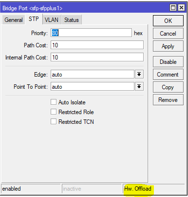
Note the Hw. Offload verification under this bridge port in the CRS317
It is important to realize that bridging in the CRS, when used for VLAN configuration is actually using the switch ASIC to forward traffic and not the CPU.
In this instance, the bridge is merely used as a familiar configuration tool to tie ports and VLANs together but does in fact allow for the forwarding of traffic in hardware at wirespeed.
Cisco to MikroTik – command translation
Cisco command
MikroTik Command
interface FastEthernet5/0/47
switchport access vlan 100
switchport mode access
end
/interface bridge port
add bridge=bridge1 interface=sfp-sfpplus1 pvid=100
interface bridge host print where interface=sfp-sfpplus1
show interfaces trunk
show vlan
interface bridge vlan print
show spanning-tree
interface bridge monitor
show etherchannel summary
interface bonding print detail
Examples of the MikroTik RouterOS commands from the table above
Untagged switch port
This command will create an untagged or “access” switch port on VLAN 100
[admin@MikroTik] > /interface bridge port add bridge=bridge1 interface=sfp-sfpplus1 pvid=100
Tagged switch port
This command will create a tagged or “trunk” switch port on VLAN 200. Additional VLANs can be tagged on a port by using the same syntax and adding a new VLAN number.
This command will set the bridge loop prevention protocol to Multiple Spanning Tree. As a general observation, MSTP tends to be the most compatible across vendors as some vendors like Cisco use a proprietary version of Rapid STP.
This is referred to as “portfast” in the Cisco world and allows a port facing a device that isn’t a bridge or a switch to transition immediately to forwarding but if it detects a BPDU, it will revert to normal STP operation. (this is the difference between edge=yes and edge=yes-discover)
[admin@MikroTik] > /interface bridge port set edge=yes-discover
LACP Bonding
This command will create a bonding interface which is similar to a Port Channel in Cisco’s switches. Two or more physical interfaces can be selected to bond together and then the 802.3ad mode is selected which is LACP. You can also select the hashing policy and ideally it should match what the device on the other end is set for to get the best distribution of traffic and avoid interoperability issues.
This print command will show all learned MAC addresses and associated VLANs in the CAM table of the switch
[admin@IPA-LAB-CRS-317] > interface bridge host print
Flags: X - disabled, I - invalid, D - dynamic, L - local, E - external
 #       MAC-ADDRESS        VID ON-INTERFACE      BRIDGE     AGE
 0   DL  64:D1:54:F0:0E:46      Po1               bridge1
 1   DL  64:D1:54:F0:0E:47      sfp-sfpplus2      bridge1
 2   D E 04:FE:7F:5C:5D:9C    1 Po1               bridge1
 3   DL  64:D1:54:F0:0E:46    1 Po1               bridge1
 4   D   00:0C:42:B2:A6:3D  200 sfp-sfpplus2      bridge1    52s
 5   D E 4C:5E:0C:23:DF:50  200 Po1               bridge1
 6   DL  64:D1:54:F0:0E:46  200 bridge1           bridge1
 7   DL  64:D1:54:F0:0E:47  200 sfp-sfpplus2      bridge1
View the MAC table for VLAN 200 in the switch
This print command will show all learned MAC addresses in VLAN 200.
[admin@IPA-LAB-CRS-317] > interface bridge host print where vid=200
Flags: X - disabled, I - invalid, D - dynamic, L - local, E - external
 #       MAC-ADDRESS        VID ON-INTERFACE           BRIDGE           AGE
 0   D   00:0C:42:B2:A6:3D  200 sfp-sfpplus2           bridge1          51s
 1   D E 4C:5E:0C:23:DF:50  200 Po1                    bridge1
 2   DL  64:D1:54:F0:0E:46  200 bridge1                bridge1
 3   DL  64:D1:54:F0:0E:47  200 sfp-sfpplus2           bridge1
View the MAC table for bonding interface Po1 in the switch
This print command will show all learned MAC addresses on port Po1.
[admin@IPA-LAB-CRS-317] > interface bridge host print where interface=Po1
Flags: X - disabled, I - invalid, D - dynamic, L - local, E - external
 #       MAC-ADDRESS        VID ON-INTERFACE           BRIDGE           AGE
 0   DL  64:D1:54:F0:0E:46      Po1                    bridge1
 1   D E 04:FE:7F:5C:5D:9C    1 Po1                    bridge1
 2   DL  64:D1:54:F0:0E:46    1 Po1                    bridge1
 3   D E 4C:5E:0C:23:DF:50  200 Po1                    bridge1
View the current VLANs configured in the switch
The bridge vlan print command will show all configured VLANs in the switch.
[admin@IPA-LAB-CRS-317] > interface bridge vlan print
Flags: X - disabled, D - dynamic
 #   BRIDGE              VLAN-IDS  CURRENT-TAGGED              CURRENT-UNTAGGED
 0   bridge1             200       bridge1                     sfp-sfpplus2
                                   Po1
 1 D bridge1             1                                     bridge1
                                                               Po1
View Bridge Spanning Tree information
The bridge monitor command will show the configuration details and current state of spanning tree including the root bridge and root port