In the world of network engineering, learning a new syntax for a NOS can be daunting if you need a specific config quickly. Juniper is a popular option for service providers/data centers and is widely deployed across the world.
This is a continuation of the Rosetta stone for network operating systems series. In this article we will be covering multi-protocol label switching (MPLS) using label distribution protocol (LDP). We are sticking with LDP as MikroTik does not have wide support for RSVP-TE.
You can find the first two articles of the series here:
Juniper to MikroTik – BGP commands
Juniper to MikroTik – OSPF commands
While many commands have almost the exact same information, others are as close as possible. Since there isn’t always an exact match, sometimes you may have to run two or three commands to get the information needed.
Using EVE-NG for testing
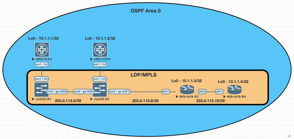
We conducted utilized EVE-NG for all of the testing with the topology seen below.
| Juniper Command | MikroTik Command |
|---|---|
| show ldp neighbor | mpls ldp neighbor print |
| show ldp interface | mpls ldp interface print |
| show route forwarding-table family mpls | mpls forwarding-table print |
| show ldp database | mpls remote-bindings print |
| show ldp database | mpls local-bindings print |
| show mpls label usage | mpls print |
| set interfaces ge-0/0/0 unit 0 family mpls set protocols ldp interface ge-0/0/0.0 | /mpls ldp interface add interface=ether1 |
| set routing-options router-id 10.1.1.1 | /mpls ldp set enabled=yes lsr-id=10.1.1.3 |
Examples of the commands above
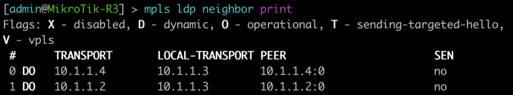
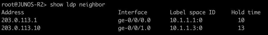
This first command will show you some basic information about your MPLS LDP neighbors. On juniper you can add the keyword detail to the end for additional information on the neighbors.
[admin@MikroTik-R3] > mpls ldp neighbor print
root@JUNOS-R2> show ldp neighbor
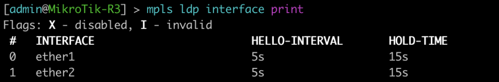
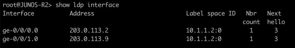
This command will list all of the interfaces that are currently enabled for LDP.
[admin@MikroTik-R3] > mpls ldp interface print
root@JUNOS-R2> show ldp interface
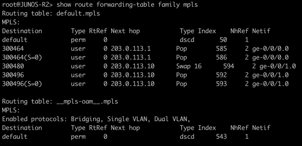
Use this command to display the MPLS forwarding table which shows what labels are assigned, the interface used and the next-hop. It will also tell you the action taken such as pop, swap, or push.
[admin@MikroTik-R3] > mpls forwarding-table print
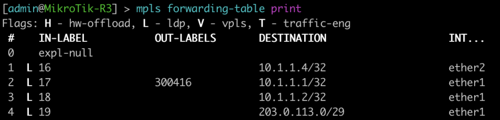
root@JUNOS-R2> show route forwarding-table family mpls
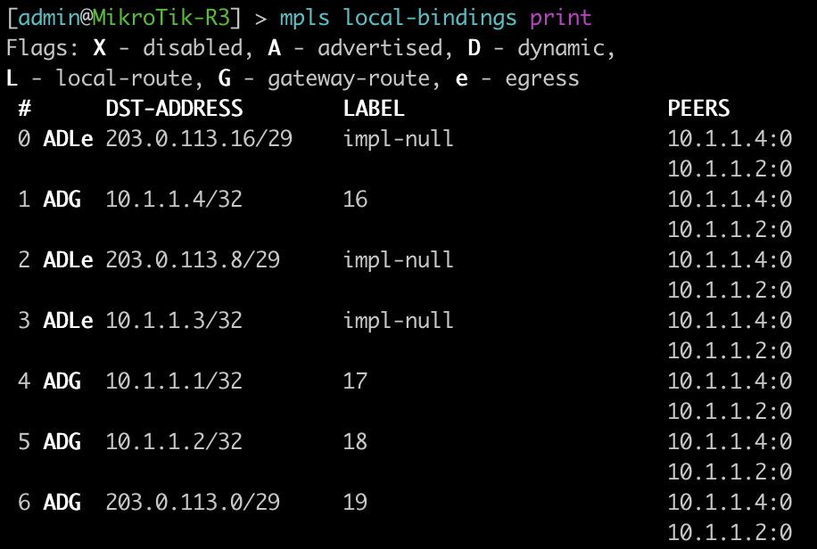
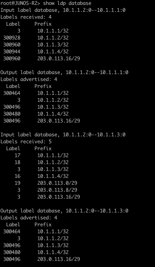
The next two commands will be combined since juniper only has one command to be equivalent to mikrotiks output. This is will show the advertised and received labels for all of the prefixes known to LDP as well as the label associated with it and where it was learned from. On JunOS you will notice label 3. This is juiper’s method to signal implicit null and request label popping by the downstream router.
[admin@MikroTik-R3] > mpls remote-bindings print
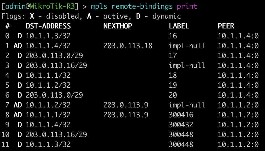
[admin@MikroTik-R3] > mpls local-bindings print
root@JUNOS-R2> show ldp database
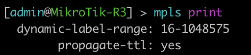
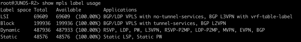
This last command will show the label ranges and what they are used for.
[admin@MikroTik-R3] > mpls print
root@JUNOS-R2> show mpls label usage
Configurations
root@JUNOS-R1# show | display set
set version 18.2R1.9
set system root-authentication encrypted-password "$6$iCt/DOMc$lQFrIQdrjot1m0lIY5A2eUaOmat87oAqbNZWd/3KPij2QWTlBQEyYlVbb1/emd2N9VKN6NL0olk.kJK7mLcgM0"
set system host-name JUNOS-R1
set system syslog user * any emergency
set system syslog file messages any notice
set system syslog file messages authorization info
set system syslog file interactive-commands interactive-commands any
set system processes dhcp-service traceoptions file dhcp_logfile
set system processes dhcp-service traceoptions file size 10m
set system processes dhcp-service traceoptions level all
set system processes dhcp-service traceoptions flag packet
set interfaces ge-0/0/0 unit 0 family inet address 203.0.113.1/29
set interfaces ge-0/0/0 unit 0 family mpls
set interfaces fxp0 unit 0 family inet dhcp vendor-id Juniper-vmx-VM6015C6C2F2
set interfaces lo0 unit 0 family inet address 10.1.1.1/32
set routing-options router-id 10.1.1.1
set protocols ospf area 0.0.0.0 interface ge-0/0/0.0
set protocols ospf area 0.0.0.0 interface lo0.0 passive
set protocols ldp interface ge-0/0/0.0
root@JUNOS-R2# show | display set
set version 18.2R1.9
set system root-authentication encrypted-password "$6$x.MmgodX$XG1D3lCYPC8VpIhE8NXxdRJaoZS8sYB2PB0v50POrrx6Mi.nhnTB/41NGFk1zL8RDQBdR/lCPG2NazFDYgzNf/"
set system host-name JUNOS-R2
set system syslog user * any emergency
set system syslog file messages any notice
set system syslog file messages authorization info
set system syslog file interactive-commands interactive-commands any
set system processes dhcp-service traceoptions file dhcp_logfile
set system processes dhcp-service traceoptions file size 10m
set system processes dhcp-service traceoptions level all
set system processes dhcp-service traceoptions flag packet
set interfaces ge-0/0/0 unit 0 family inet address 203.0.113.2/29
set interfaces ge-0/0/0 unit 0 family mpls
set interfaces ge-0/0/1 unit 0 family inet address 203.0.113.9/29
set interfaces ge-0/0/1 unit 0 family mpls
set interfaces fxp0 unit 0 family inet dhcp vendor-id Juniper-vmx-VM6015C6C3B3
set interfaces lo0 unit 0 family inet address 10.1.1.2/32
set routing-options router-id 10.1.1.2
set protocols ospf area 0.0.0.0 interface ge-0/0/0.0
set protocols ospf area 0.0.0.0 interface ge-0/0/1.0
set protocols ospf area 0.0.0.0 interface lo0.0 passive
set protocols ldp interface ge-0/0/0.0
set protocols ldp interface ge-0/0/1.0[admin@MikroTik-R3] > export
# jan/31/2021 20:52:19 by RouterOS 6.46.8
# software id =
#
#
#
/interface bridge
add name=Loopback0
/interface wireless security-profiles
set [ find default=yes ] supplicant-identity=MikroTik
/ip address
add address=203.0.113.10/29 interface=ether1 network=203.0.113.8
add address=10.1.1.3 interface=Loopback0 network=10.1.1.3
add address=203.0.113.17/29 interface=ether2 network=203.0.113.16
/ip dhcp-client
add disabled=no interface=ether2
add disabled=no interface=ether1
/mpls ldp
set enabled=yes lsr-id=10.1.1.3
/mpls ldp interface
add interface=ether1
add interface=ether2
/routing ospf network
add area=backbone network=203.0.113.8/29
add area=backbone network=10.1.1.3/32
add area=backbone network=203.0.113.16/29
/system identity
set name=MikroTik-R3[admin@MikroTik-R4] > export
# jan/31/2021 21:06:10 by RouterOS 6.46.8
# software id =
#
#
#
/interface bridge
add name=Loopback0
/interface wireless security-profiles
set [ find default=yes ] supplicant-identity=MikroTik
/ip address
add address=203.0.113.18/29 interface=ether1 network=203.0.113.16
add address=10.1.1.4 interface=Loopback0 network=10.1.1.4
/ip dhcp-client
add disabled=no interface=ether2
add disabled=no interface=ether1
/mpls ldp
set enabled=yes lsr-id=10.1.1.4
/mpls ldp interface
add interface=ether1
/routing ospf network
add area=backbone network=203.0.113.16/29
add area=backbone network=10.1.1.4/32
/system identity
set name=MikroTik-R4Thanks for joining us for this series and check back soon for more posts.
]]>In the world of network engineering, learning a new syntax for a NOS can be daunting if you need a specific config quickly. Juniper is a popular option for service providers/data centers and is widely deployed across the world.
This is a continuation of the Rosetta stone for network operating systems series. In this portion of the series we will be covering Open Shortest Path First, OSPF, version 2 which is a popular interior gateway protocol (IGP).
You can find the first article of the series Juniper to Mikrotik – BGP Commands here.
While many commands have almost the exact same information, others are as close as possible. Since there isn’t always an exact match, sometimes you may have to run two or three commands to get the information needed.
Using EVE-NG for testing
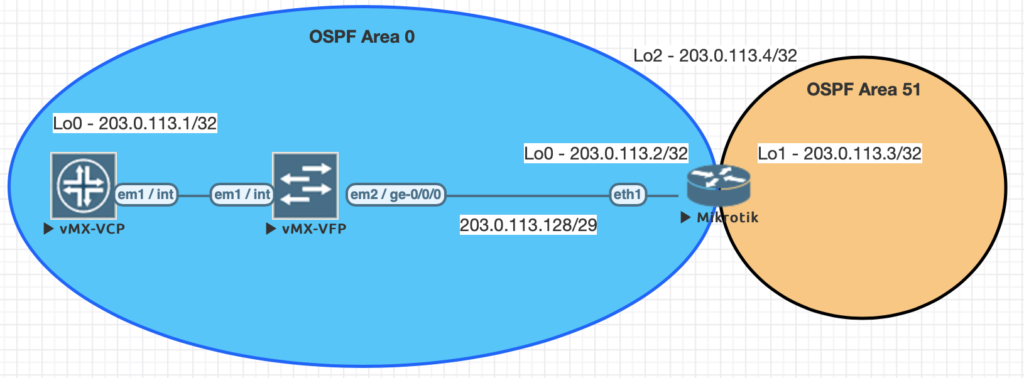
We conducted all testing on EVE-NG utilizing the topology seen below.
| JunOS Command | MikroTik Command |
|---|---|
| show ospf neighbor | routing ospf neighbor print |
| show ospf interface | routing ospf interface print |
| show ospf overview brief | routing ospf instance print detail |
| show ospf database | routing ospf lsa print |
| show route protocol ospf | ip route print where ospf=yes |
| show ospf route abr | routing ospf area-border-router print |
| show ospf route asbr | routing ospf as-border-router print |
| edit protocols ospf | /routing ospf instance |
| set routing-options router-id 203.0.113.1 | /routing ospf instance set 0 router-id=203.0.113.2 |
| set protocols ospf area 0.0.0.0 interface lo0.0 | /routing ospf network add area=backbone network=203.0.113.2/32 |
| set protocols ospf area 0.0.0.0 interface ge-0/0/0.0 | /routing ospf network add area=backbone network=203.0.113.128/29 |
| set protocols ospf area 0.0.0.0 interface ge-0/0/0.0 interface-type p2p set protocols ospf area 0.0.0.0 interface ge-0/0/0.0 hello-interval 1 set protocols ospf area 0.0.0.0 interface ge-0/0/0.0 dead-interval 4 | /routing ospf interface add dead-interval=4s hello-interval=1s interface=ether1 network-type=point-to-point |
Examples of the commands above
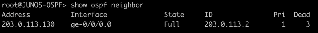
This first command will show you all of the routers you have an OSPF neighbor adjacency with.
[admin@MIKROTIK-OSPF] > routing ospf neighbor print

root@JUNOS-OSPF> show ospf neighbor
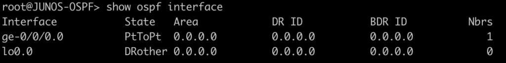
This next command lists all of the interface enabled for OSPF as well as some basic information such as cost, priority, and network type. Juniper displays slightly different information such as area, DR info, and number of neighbors. Juniper does not have the concept of a network statement so interfaces explicitly configured for OSPF will appear here. You can optionally add the detail command on JunOS for more information.
[admin@MIKROTIK-OSPF] > routing ospf interface print
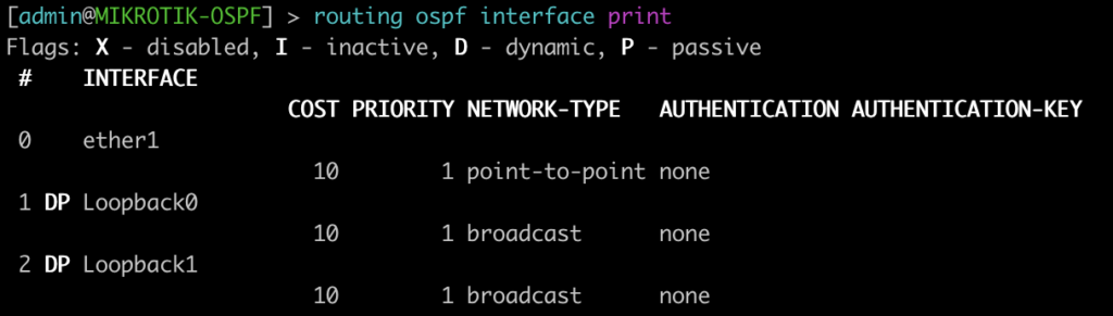
root@JUNOS-OSPF> show ospf interface
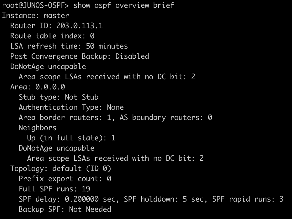
This command will list all of the details regarding the OSPF instances running on the router.
[admin@MIKROTIK-OSPF] > routing ospf instance print
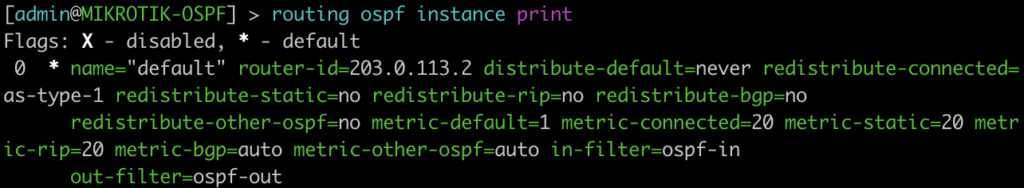
root@JUNOS-OSPF> show ospf overview brief
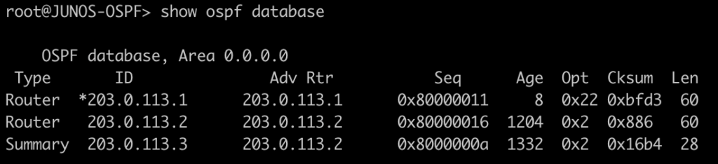
This command lists all of the OSPF LSAs as well as some details about them.
[admin@MIKROTIK-OSPF] > routing ospf lsa print
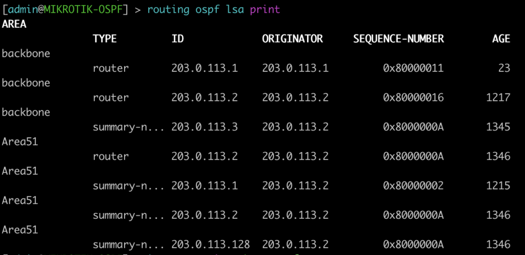
root@JUNOS-OSPF> show ospf database
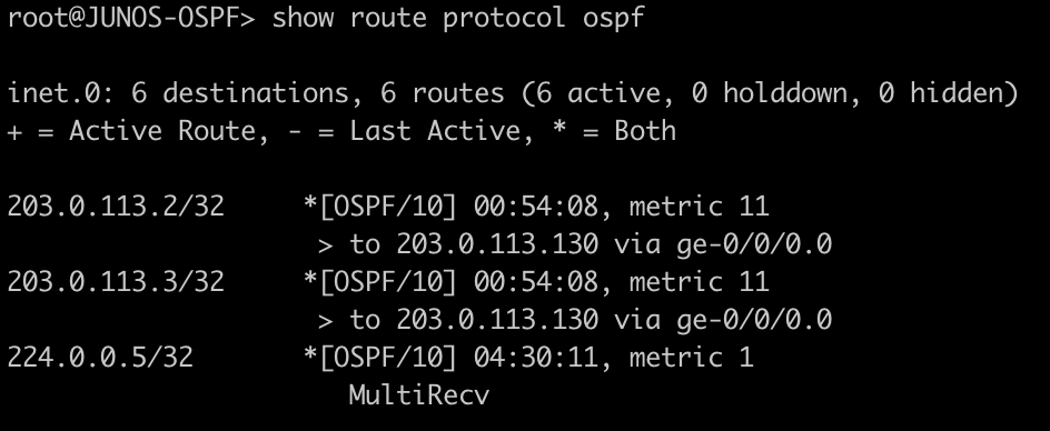
This next command will show all of the OSPF routes in the routing table.
[admin@MIKROTIK-OSPF] > ip route print where ospf=yes
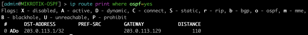
root@JUNOS-OSPF> show route protocol ospf
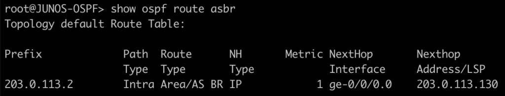
This next set of commands will show you the area-border-routers or autonomous-system-boundary routers. We injected a connected route into OSPF to generate a type-5 LSA for an external route.
[admin@MIKROTIK-OSPF] > routing ospf area-border-router print
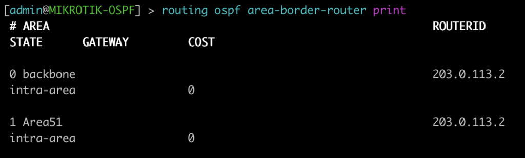
[admin@MIKROTIK-OSPF] > routing ospf as-border-router print
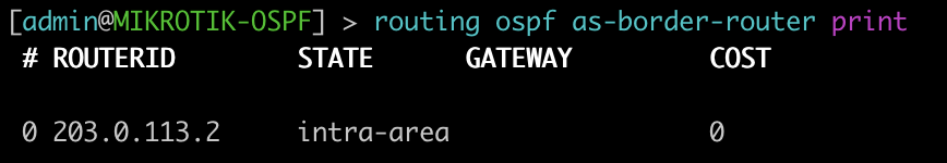
root@JUNOS-OSPF> show ospf route abr
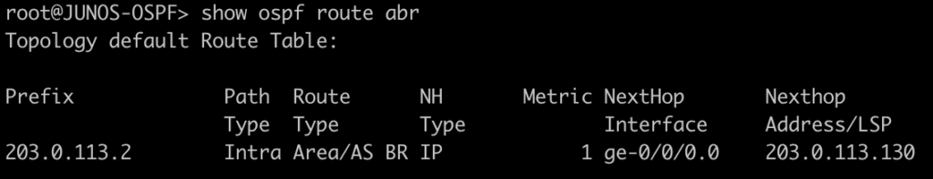
root@JUNOS-OSPF> show ospf route asbr
Mikrotik OSPF configuration
/interface bridge
add name=Loopback0
add name=Loopback1
add name=Loopback2
/interface wireless security-profiles
set [ find default=yes ] supplicant-identity=MikroTik
/routing ospf area
add area-id=0.0.0.51 name=Area51
/routing ospf instance
set [ find default=yes ] redistribute-connected=as-type-1 router-id=203.0.113.2
/ip address
add address=203.0.113.2 interface=Loopback0 network=203.0.113.2
add address=203.0.113.3 interface=Loopback1 network=203.0.113.3
add address=203.0.113.4 interface=Loopback2 network=203.0.113.4
add address=203.0.113.130/29 interface=ether1 network=203.0.113.128
/ip dhcp-client
add dhcp-options=hostname,clientid disabled=no interface=ether1
/routing ospf interface
add dead-interval=4s hello-interval=1s interface=ether1 network-type=point-to-point
/routing ospf network
add area=backbone network=203.0.113.2/32
add area=backbone network=203.0.113.128/29
add area=Area51 network=203.0.113.3/32
/system identity
set name=MIKROTIK-OSPF
Juniper OSPF configuration
set interfaces ge-0/0/0 unit 0 family inet address 203.0.113.129/29
set interfaces lo0 unit 0 family inet address 203.0.113.1/32
set routing-options router-id 203.0.113.1
set protocols ospf area 0.0.0.0 interface ge-0/0/0.0 interface-type p2p
set protocols ospf area 0.0.0.0 interface ge-0/0/0.0 hello-interval 1
set protocols ospf area 0.0.0.0 interface ge-0/0/0.0 dead-interval 4
set protocols ospf area 0.0.0.0 interface lo0.0 passive
More Juniper to MikroTik articles are on the way!
This article covered some of basic and common OSPF commands. Check back in the future for examples of more advanced features and capabilities. Also stay tuned for our upcoming Juniper to MikroTik MPLS command translation.
]]>Juniper to MikroTik – a new series
Previously, I’ve written a number of articles that compared syntax between Cisco and MikroTik and have received some great feedback on them.
As such, I decided to begin a series on Juniper to MikroTik starting with MPLS and L3VPN interop as it related to a project I was working on last year.
In the world of network engineering, learning a new syntax for a NOS can be overwhelming if you need a specific set of config in a short timeframe. The command structure for RouterOS can be a bit challenging if you are used to Juniper CLI commands.
If you’ve worked with Juniper gear and are comfortable with how to deploy that vendor, it is helpful to draw comparisons between the commands, especially if you are trying to build a network with a MikroTik and Juniper router.
Lab Overview
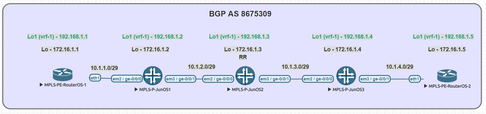
The lab consists of (3) Juniper P routers and (2) MikroTik PE routers. Although we did not get into L3VPN in this particular lab, the layout is the same.
A note on route-targets
It seems that the format of the route-target has some bearing on this being successful. Normally i’ll use a format like 8675309:1 but in this case, I had some interop issues with making that work so we used dotted decimal.
Some of the results when searching seem to suggest that platforms like Juniper and Cisco reverse the RT string in the packet while MikroTik uses it in sequential order
To work around that, the format we used was the same forwards and backwards – 1.1.1.1:1
MPLS and VPNv4 use case
MPLS is often used in service provider and data center networks to provide multi-tenancy.
VPNv4 specifically allows for separate routing tables to be created (VRFs) and advertised via BGP using the VPNv4 address family.
This address family relies on MPLS to assign a VPN label and route target as an extended community to the route which keeps it isolated from routes in other VRFs.
Practical Use
Many service provider networks rely on Juniper for the edge and core roles.
However, increasingly, ISPs want to save money on last mile and smaller aggregation points.
MikroTik is an effective choice for more simplistic MPLS capabilities as it’s inexpensive and interops with Juniper.
This creates a variety of low cost deployment options as a manged CE router, GPON aggregation in the last mile, managed CE for enterprise customers….and so on.
Command comparison
| Juniper command | MikroTik Command |
|---|---|
| > show ldp neighbor | mpls ldp neighbor print |
| > show mpls interface | mpls ldp interface print |
| > show route table mpls.0 | mpls forwarding-table print |
| > show ldp database | mpls remote-bindings print |
| > show ldp database | mpls local-bindings print |
| > show mpls label usage label-range | mpls print |
| > show ldp overview | mpls ldp print |
| # set interfaces ge-0/0/0 unit 0 family mpls # set protocols mpls interface ge-0/0/0.0 # set protocols ldp interface ge-0/0/0.0 | /mpls ldp interface add interface=ether1 |
| { inherited from loopback } | /mpls ldp set enabled=yes lsr-id=10.1.1.3 |
Testing connectivity
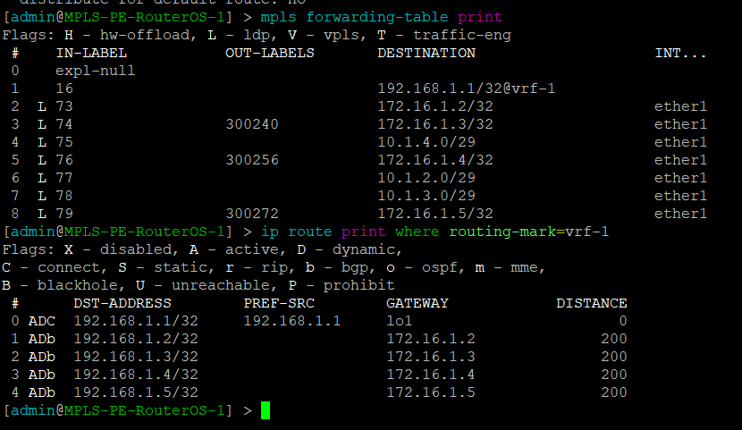
MikroTik – mpls forwarding table and vrf routes
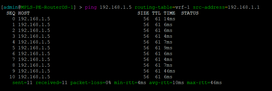
MikroTik – Ping PE2 through Juniper MPLS network
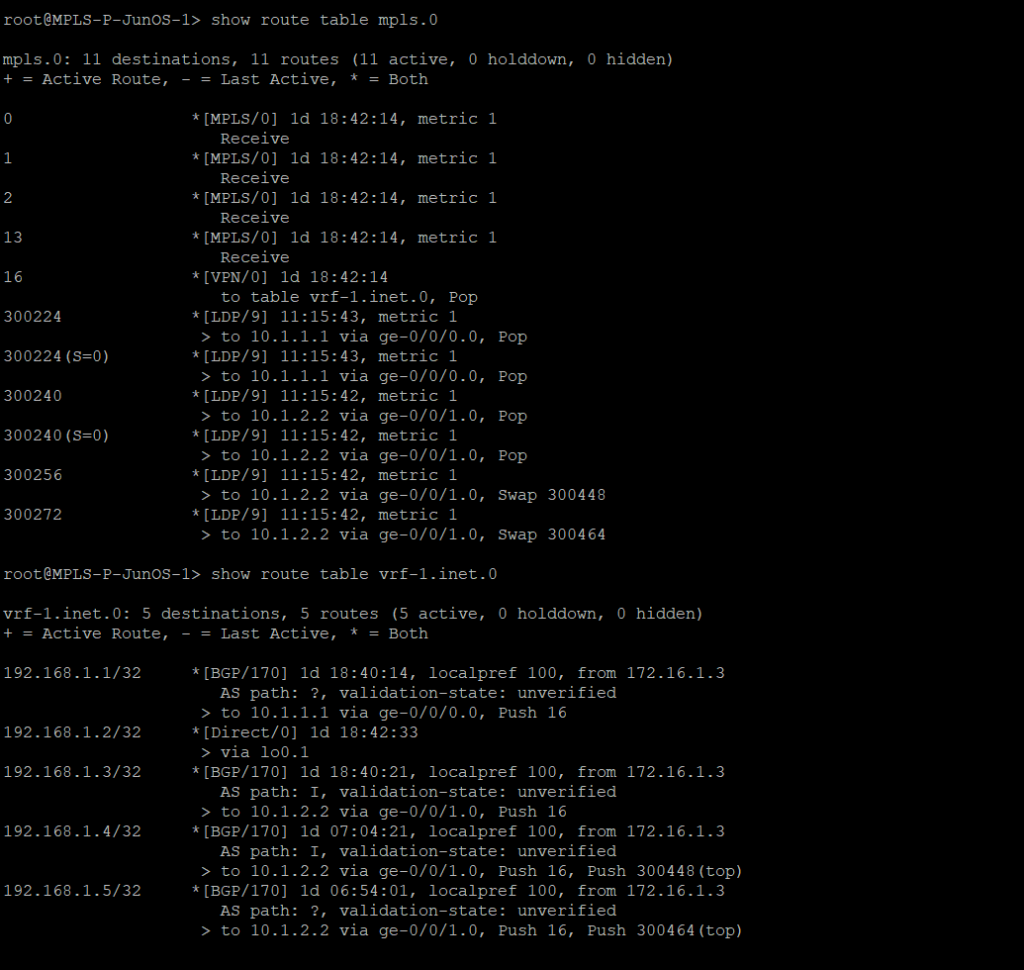
Juniper – mpls forwarding table and vrf routes
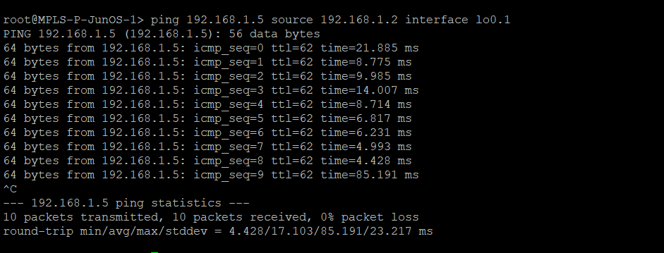
Juniper – Ping PE2 from Juniper MPLS network
Router configs
MPLS-PE-RouterOS-1
/interface bridge
 add name=lo0
 add name=lo1
 /interface wireless security-profiles
 set [ find default=yes ] supplicant-identity=MikroTik
 /routing bgp instance
 set default as=8675309
 /ip address
 add address=10.1.1.1/29 interface=ether1 network=10.1.1.0
 add address=192.168.1.1 interface=lo1 network=192.168.1.1
 add address=172.16.1.1 interface=lo0 network=172.16.1.1
 /ip dhcp-client
 add disabled=no interface=ether1
 /ip route vrf
 add export-route-targets=1.1.1.1:1 import-route-targets=1.1.1.1:1 interfaces=\
     lo1 route-distinguisher=1.1.1.1:1 routing-mark=vrf-1
 /mpls ldp
 set enabled=yes lsr-id=172.16.1.1 transport-address=172.16.1.1
 /mpls ldp interface
 add interface=ether1
 /routing bgp instance vrf
 add redistribute-connected=yes routing-mark=vrf-1
 /routing bgp peer
 add address-families=ip,vpnv4 name=peer1 remote-address=172.16.1.3 remote-as=\
     8675309 update-source=lo0
 /routing ospf network
 add area=backbone network=10.1.1.0/29
 add area=backbone network=172.16.1.1/32
 /system identity
 set name=MPLS-PE-RouterOS-1
MPLS-PE-RouterOS-2
/interface bridge
 add name=lo0
 add name=lo1
 /interface wireless security-profiles
 set [ find default=yes ] supplicant-identity=MikroTik
 /routing bgp instance
 set default as=8675309
 /ip address
 add address=10.1.4.2/29 interface=ether1 network=10.1.4.0
 add address=192.168.1.5 interface=lo1 network=192.168.1.5
 add address=172.16.1.5 interface=lo0 network=172.16.1.5
 /ip dhcp-client
 add disabled=no interface=ether1
 /ip route vrf
 add export-route-targets=1.1.1.1:1 import-route-targets=1.1.1.1:1 interfaces=lo1 route-distinguisher=1.1.1.1:1 routing-mark=vrf-1
 /mpls ldp
 set enabled=yes lsr-id=172.16.1.5 transport-address=172.16.1.5
 /mpls ldp interface
 add interface=ether1
 /routing bgp instance vrf
 add redistribute-connected=yes routing-mark=vrf-1
 /routing bgp peer
 add address-families=ip,vpnv4 name=peer1 remote-address=172.16.1.3 remote-as=8675309 update-source=lo0
 /routing ospf network
 add area=backbone network=10.1.4.0/29
 add area=backbone network=172.16.1.5/32
 /system identity
 set name=MPLS-PE-RouterOS-2
MPLS-P-JunOS-1
version 14.1R1.10;
 system {
     host-name MPLS-P-JunOS-1;
     root-authentication {
         encrypted-password "$1$kj9Pva8c$R0knN0l873H.UaBUUNYA00"; ## SECRET-DATA
     }
     syslog {
         user * {
             any emergency;
         }
         file messages {
             any notice;
             authorization info;
         }
         file interactive-commands {
             interactive-commands any;
         }
     }
 }
 interfaces {
     ge-0/0/0 {
         unit 0 {
             family inet {
                 address 10.1.1.2/29;
             }
             family mpls;
         }
     }
     ge-0/0/1 {
         unit 0 {
             family inet {
                 address 10.1.2.1/29;
             }
             family mpls;
         }
     }
     lo0 {
         unit 0 {
             family inet {
                 address 172.16.1.2/32;
             }
         }
         unit 1 {
             family inet {
                 address 192.168.1.2/32;
             }
         }
     }
 }
 routing-options {
     router-id 172.16.1.2;
     route-distinguisher-id 172.16.1.2;
     autonomous-system 8675309;
 }
 protocols {
     mpls {
         traffic-engineering mpls-forwarding;
         interface ge-0/0/0.0;
         interface ge-0/0/1.0;
     }
     bgp {
         group rr {
             type internal;
             local-address 172.16.1.2;
             family inet-vpn {
                 unicast;
             }
             neighbor 172.16.1.3 {
                 peer-as 8675309;
             }
         }
     }
     ospf {
         traffic-engineering;
         area 0.0.0.0 {
             interface ge-0/0/0.0;
             interface ge-0/0/1.0;
             interface lo0.0;
         }
     }
     ldp {
         interface ge-0/0/0.0;
         interface ge-0/0/1.0;
     }
 }
 routing-instances {
     vrf-1 {
         instance-type vrf;
         interface lo0.1;
         route-distinguisher 1.1.1.1:1;
         vrf-target target:1.1.1.1:1;
         vrf-table-label;
     }
 }
MPLS-P-JunOS-2
version 14.1R1.10;
 system {
     host-name MPLS-P-JunOS-2;
     root-authentication {
         encrypted-password "$1$g6tJMNPd$f35BMnnPgit/YLshrXd/L1"; ## SECRET-DATA
     }
     services {
         ssh;
     }
     syslog {
         user * {
             any emergency;
         }
         file messages {
             any notice;
             authorization info;
         }
         file interactive-commands {
             interactive-commands any;
         }
     }
 }
 interfaces {
     ge-0/0/0 {
         unit 0 {
             family inet {
                 address 10.1.2.2/29;
             }
             family mpls;
         }
     }
     ge-0/0/1 {
         unit 0 {
             family inet {
                 address 10.1.3.1/29;
             }
             family mpls;
         }
     }
     lo0 {
         unit 0 {
             family inet {
                 address 172.16.1.3/32;
             }
         }
         unit 1 {
             family inet {
                 address 192.168.1.3/32;
             }
         }
     }
 }
 routing-options {
     router-id 172.16.1.3;
     route-distinguisher-id 172.16.1.3;
     autonomous-system 8675309;
 }
 protocols {
     mpls {
         traffic-engineering mpls-forwarding;
         interface ge-0/0/0.0;
         interface ge-0/0/1.0;
     }
     bgp {
         group rr {
             type internal;
             local-address 172.16.1.3;
             family inet-vpn {
                 unicast;
             }
             cluster 1.1.1.1;
             neighbor 172.16.1.2 {
                 peer-as 8675309;
             }
             neighbor 172.16.1.1 {
                 peer-as 8675309;
             }
             neighbor 172.16.1.3 {
                 peer-as 8675309;
             }
             neighbor 172.16.1.4 {
                 peer-as 8675309;
             }
             neighbor 172.16.1.5 {
                 peer-as 8675309;
             }
         }
     }
     ospf {
         traffic-engineering;
         area 0.0.0.0 {
             interface ge-0/0/0.0;
             interface ge-0/0/1.0;
             interface lo0.0;
         }
     }
     ldp {
         interface ge-0/0/0.0;
         interface ge-0/0/1.0;
     }
 }
 policy-options {
     policy-statement import-vrf1 {
         term import-term-connected {
             from protocol direct;
             then accept;
         }
         term term-reject {
             then reject;
         }
     }
 }
 routing-instances {
     vrf-1 {
         instance-type vrf;
         interface lo0.1;
         route-distinguisher 1.1.1.1:1;
         vrf-target target:1.1.1.1:1;
         vrf-table-label;
     }
 }
MPLS-P-JunOS-3
version 14.1R1.10;
 system {
     host-name MPLS-P-JunOS-3;
     root-authentication {
         encrypted-password "$1$kj9Pva8c$R0knN0l873H.UaBUUNYA00"; ## SECRET-DATA
     }
     syslog {
         user * {
             any emergency;
         }
         file messages {
             any notice;
             authorization info;
         }
         file interactive-commands {
             interactive-commands any;
         }
     }
 }
 interfaces {
     ge-0/0/0 {
         unit 0 {
             family inet {
                 address 10.1.3.2/29;
             }
             family mpls;
         }
     }
     ge-0/0/1 {
         unit 0 {
             family inet {
                 address 10.1.4.1/29;
             }
             family mpls;
         }
     }
     lo0 {
         unit 0 {
             family inet {
                 address 172.16.1.4/32;
             }
         }
         unit 1 {
             family inet {
                 address 192.168.1.4/32;
             }
         }
     }
 }
 routing-options {
     router-id 172.16.1.4;
     route-distinguisher-id 172.16.1.4;
     autonomous-system 8675309;
 }
 protocols {
     mpls {
         traffic-engineering mpls-forwarding;
         interface ge-0/0/0.0;
         interface ge-0/0/1.0;
     }
     bgp {
         group rr {
             type internal;
             local-address 172.16.1.4;
             family inet-vpn {
                 unicast;
             }
             neighbor 172.16.1.3 {
                 peer-as 8675309;
             }
         }
     }
     ospf {
         traffic-engineering;
         area 0.0.0.0 {
             interface ge-0/0/0.0;
             interface ge-0/0/1.0;
             interface lo0.0;
         }
     }
     ldp {
         interface ge-0/0/0.0;
         interface ge-0/0/1.0;
     }
 }
 routing-instances {
     vrf-1 {
         instance-type vrf;
         interface lo0.1;
         route-distinguisher 1.1.1.1:1;
         vrf-target target:1.1.1.1:1;
         vrf-table-label;
     }
 }
]]>The challenge of adding IPv6 to your WISP
IPv6 is one of those technologies that can feel pretty overwhelming, but it doesn’t have to be. Many of the same ideas and concepts learned in IPv4 networking still apply.
This guide is meant to give you an overview of an example IPv6 addressing plan for an entire WISP as well as the config needed in MikroTik to deploy IPv6 from a core router all the way to a subscriber device.
Benefits of adding IPv6
- Public addressing for all subscribers – reduced need for NAT
- Regulatory compliance – public addressing that is persistent makes it much easier to be compliant for things like CALEA
- Reduced complaints from gamers – Xbox and Playstation both have IPv6 networks and prefer IPv6. This reduces complaints from customers who have gaming consoles that have detected an “improper” NAT configuration.
- Increased security – IPv6, while not impervious to security threats makes it much harder for attackers to scan IPs due to the sheer size of the IP space. If using privacy extensions with SLAAC, it also makes it much harder to target someone online as the IP address seen on the internet changes randomly.
- Improved real time communications – one way audio and video issues are often caused by NAT. Using end to end connectivity on public addressing improves the reliability of IP voice and video when used on IPv6
- Web scale content (Netflix, Facebook, Google, etc) is IPv6 enabled which means a large portion of your traffic will shift to native IPv6 once dual stack is enabled.
IPv6 Addressing
One of the things i’ve learned about IPv6 is that addressing plans seem to spark epic debates about the waste of addresses and what size prefix an end subscriber should get.
Although this lab could have easily been done with a /56 at the tower and /53 at each AP, I decided to use RIPEs recommendations from their guide on IPv6 best operational practices.
This is mainly to keep the focus of the article on actually getting IPv6 deployed and not focusing on the addressing.
Dual Stack
For simplicity, the IPv4 config is not shown, but the recommended design for an operational WISP is to implement IPv4 and IPv6 side by side in a Dual Stack configuration.
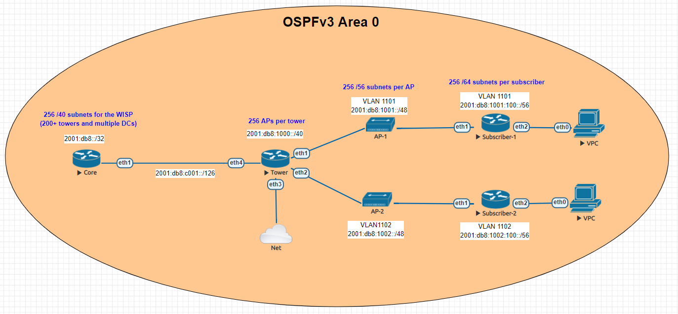
Lab Overview
The lab is designed to illustrate most of the operational aspects of IPv6 in a WISP using MikroTik CHR routers in EVE-NG. This includes:
- DHCPv6 and Prefix Delegation (PD)
- OSPFv3 single area configuration and origination of a default route
- Subscriber router example with SLAAC
Core Router

In the lab, the core router is shown directly connected to the tower for simplicity, in your WISP, there may be multiple towers between the core and the end of the network.
The concept, however is the same – use /126 addressing to connect towers for OSPFv3.
Note that OSPFv3 still requires a router-id in dotted decimal format, even though the address you put int doesn’t have to actually exist – for consistency however, use the IPv4 loopback of the router for the router id.
The internet connectivity isn’t shown in this lab, but your ISP will give you a /126 address to connect to your border router and either peer with BGP or the provider can route the /32 prefix to you.
Config
/interface wireless security-profiles
set [ find default=yes ] supplicant-identity=MikroTik
/routing ospf-v3 instance
set [ find default=yes ] distribute-default=always-as-type-1 router-id=\
    100.127.1.1
/ip dhcp-client
add disabled=no interface=ether1
/ipv6 address
add address=2001:db8:c001::1/126 advertise=no interface=ether1
/routing ospf-v3 interface
add area=backbone interface=ether1
/system identity
set name=Core
/tool romon
set enabled=yes
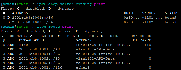
Tower Router
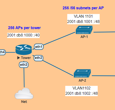
The tower router is handling most of the work as it is responsible for DHCPv6 and Prefix Delegation as well as advertising the /48 AP subnets into OSPF
In this lab , the APs are split into separate VLANs (with dual stack, IPv4 would exist on the same VLAN).
The router is configured to hand out /56 prefixes to the end subscriber using a pool of /48 per AP.
Because Prefix Delegation is being utilized, a dynamic static route is created for each /56 the DHCPv6 server hands out which eliminates the need to use a routing protocol.
Prefix Delegation in action
This example shows the prefixes allocated by the router and the dynamic static routes created
Config
/interface bridge
add name=Lo0
/interface vlan
add interface=ether1 name=vlan1101-AP1-Data vlan-id=1101
add interface=ether2 name=vlan1102-AP2-Data vlan-id=1102
/interface wireless security-profiles
set [ find default=yes ] supplicant-identity=MikroTik
/ipv6 dhcp-server
add address-pool=vl101-v6-pd-pool interface=vlan1101-AP1-Data name=\
    vl101-v6-pd
add address-pool=vl102-v6-pd-pool interface=vlan1102-AP2-Data name=\
    vl102-v6-pd
/ipv6 pool
add comment="VLAN1101 IPv6 prefix delegation pool" name=vl101-v6-pd-pool \
    prefix=2001:db8:1001::/48 prefix-length=56
add comment="VLAN1102 IPv6 prefix delegation pool" name=vl102-v6-pd-pool \
    prefix=2001:db8:1002::/48 prefix-length=56
/routing ospf-v3 instance
set [ find default=yes ] router-id=100.127.1.2
/ip dhcp-client
add disabled=no interface=ether1
/ipv6 address
add address=2001:db8:1001::1/48 advertise=no interface=vlan1101-AP1-Data
add address=2001:db8:1002::1/48 advertise=no interface=vlan1102-AP2-Data
add address=2001:db8:c001::2/126 advertise=no interface=ether4
/ipv6 nd
add interface=vlan1101-AP1-Data managed-address-configuration=yes \
    other-configuration=yes
add interface=vlan1102-AP2-Data managed-address-configuration=yes \
    other-configuration=yes
/ipv6 nd prefix
add autonomous=no interface=vlan1101-AP1-Data
add autonomous=no interface=vlan1102-AP2-Data
/routing ospf-v3 interface
add area=backbone interface=ether4
add area=backbone interface=vlan1101-AP1-Data
add area=backbone interface=vlan1102-AP2-Data
add area=backbone passive=yes
/system identity
set name=Tower
/tool romon
set enabled=yes
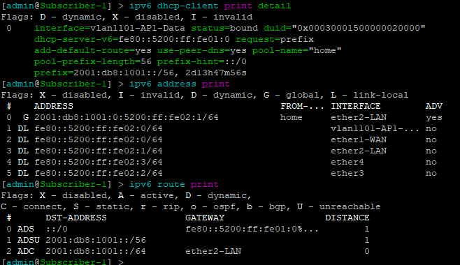
Subscriber Routers

For simplicity, MikroTik is used as the Subscriber or CPE router to provide an example of how the /56 prefix is received from the tower router and handed off to devices inside the subscriber’s home.
In this lab, the “WAN” interface or ether1 has a DHCPv6 client configured to receive the prefix from the tower router.
Ether2 or the “LAN” side, which would include a bridge of the the wireless/wired interfaces in a real router is configured with a dynamic /64 from the /56 pool and is set for SLAAC to give devices on this segment an IPv6 address.
DHCPv6 client and subscriber addresses/routes
Config – Subscriber 1
/interface ethernet
set [ find default-name=ether1 ] name=ether1-WAN
set [ find default-name=ether2 ] name=ether2-LAN
/interface vlan
add interface=ether1-WAN name=vlan1101-AP1-Data vlan-id=1101
/interface wireless security-profiles
set [ find default=yes ] supplicant-identity=MikroTik
/ip dhcp-client
add disabled=no interface=ether1-WAN
/ipv6 address
add eui-64=yes from-pool=home interface=ether2-LAN
/ipv6 dhcp-client
add add-default-route=yes interface=vlan1101-AP1-Data pool-name=home \
    pool-prefix-length=56 request=prefix
/ipv6 nd
add hop-limit=64 interface=ether2-LAN
/system identity
set name=Subscriber-1
/tool romon
set enabled=yes
Config – Subscriber 2
/interface ethernet
set [ find default-name=ether1 ] name=ether1-WAN
set [ find default-name=ether2 ] name=ether2-LAN
/interface vlan
add interface=ether1-WAN name=vlan1102-AP2-Data vlan-id=1102
/interface wireless security-profiles
set [ find default=yes ] supplicant-identity=MikroTik
/ip dhcp-client
add disabled=no interface=ether1-WAN
/ipv6 address
add eui-64=yes from-pool=home interface=ether2-LAN
/ipv6 dhcp-client
add add-default-route=yes interface=vlan1102-AP2-Data pool-name=home \
    pool-prefix-length=56 request=prefix
/ipv6 nd
add hop-limit=64 interface=ether2-LAN
/system identity
set name=Subscriber-2
/tool romon
set enabled=yes
Subscriber Device
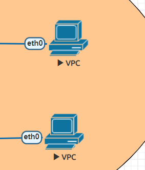
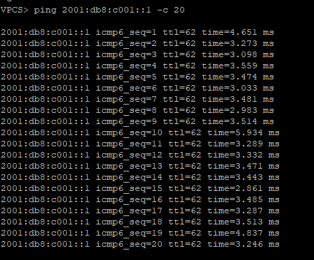
EVE-NG has a small Linux image that can be used as a host called VPC or virtual PC. This allows us to put a device on ether2 and test end to end reachability back to the core router.
SLAAC addressing example

Ping test back to the core router
Success!!!!!!!!
ISPs that use MikroTik are always looking for new ways to deliver services to customers and expand their offerings. Delivering Layer 2 at scale for customers is a design challenge that comes up frequently.
While it’s easy enough to build a VLAN nested inside of another VLAN (see below), this requires you to build all of the VLANs a customer wants to use into the PE router or handoff switch.
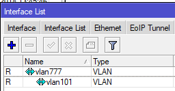
However, if you have a client that needs a layer 2 service delivered to two or more points and wants to be able to treat it just like an 802.1q trunk and add VLANs in an ad-hoc way, then using the S-Tag feature in RouterOS along with VPLS transport is a great option.
What’s the S-tag do???
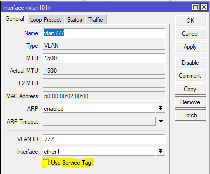
Clients will often ask me “what’s the S-Tag check box for?”
So a little background on this, there is a protocol for using outer and inner VLAN tags specified in IEEE 802.1ad that uses Service Tag (or S-Tag) to denote the outer VLAN tag used to transport Customer Tags (or C-Tags).
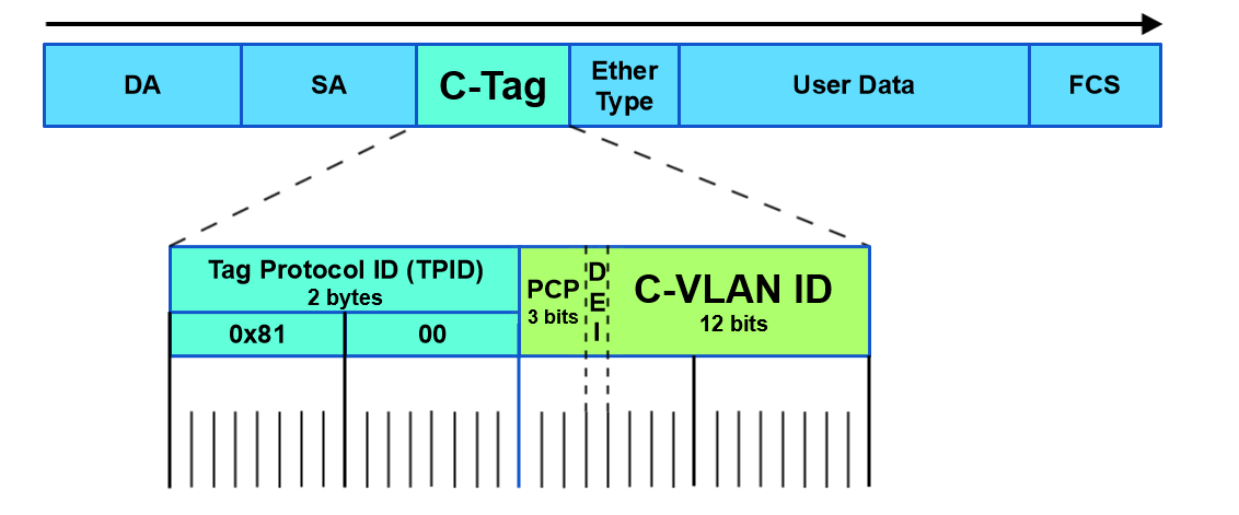
What makes the S-Tag/C-Tag a little bit different is that it actually changes the ethertype of the Frame.
| Protocol | Ethertype |
|---|---|
| 802.1q (Normal VLAN Tags) | 0x8100 |
| 802.1ad (S-tag) | 0x88a8 |
Here is an overview of the frame format of each and links to the Metro Ethernet Forum Wiki for more info.
S-Tag
https://wiki.mef.net/display/CESG/S-Tag

C-Tag
https://wiki.mef.net/display/CESG/C-Tag
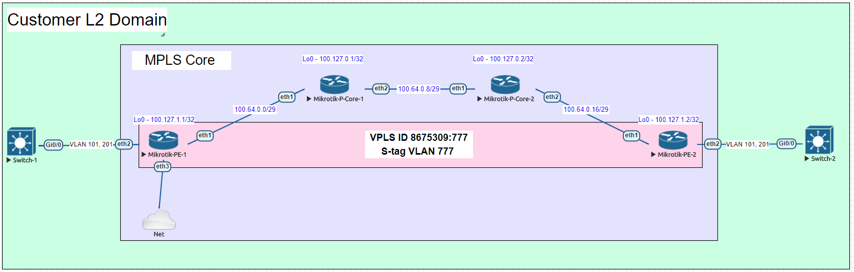
Lab Scenario
Here is a very common example of a deployment for a Layer 2 service to an end customer that rides on top of the ISP MPLS core.
In this lab we are using Cisco switches trunked to each other using VLAN 101 and 201 over a VPLS pseudowire with an S-Tag of 777.
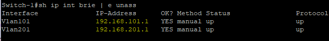
After configuring the P routers, PE routers and Cisco switches, let’s take a look at the Cisco switch and see if we can ping the SVI on the other switch on both trunked VLANs.
Here are the subnets used on the customer side:
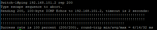
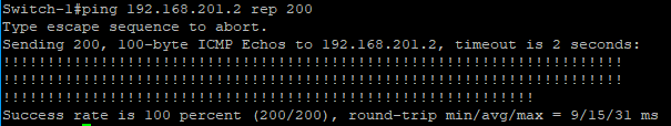
Now let’s ping the .2 address for each VLAN on Switch-2
VLAN 101
VLAN 201
Notes on MTU
A note on MTU sizing, in order to hand off a 1500 byte packet with VPLS, you normally need an MPLS and L2MTU of 1530 bytes. In order to pass a second VLAN tag you’ll want to make sure your network equipment can go up to 1534 for Layer 2 and MPLS MTUs to pass 1500 byte packet with S-Tag.
Configs for the lab
In the section below, here are all the configs for this deployment
Cisco Switch-1
version 15.2
service timestamps debug datetime msec
service timestamps log datetime msec
no service password-encryption
service compress-config
!
hostname Switch-1
!
boot-start-marker
boot-end-marker
!
!
!
no aaa new-model
!
!
!
!
!
!
!
!
ip cef
no ipv6 cef
!
!
!
spanning-tree mode pvst
spanning-tree extend system-id
!
vlan internal allocation policy ascending
!
!
!
!
!
!
!
!
!
!
!
!
!
!
interface GigabitEthernet0/0
 switchport trunk encapsulation dot1q
 switchport mode trunk
 media-type rj45
 negotiation auto
!
interface GigabitEthernet0/1
 media-type rj45
 negotiation auto
!
interface GigabitEthernet0/2
 media-type rj45
 negotiation auto
!
interface GigabitEthernet0/3
 media-type rj45
 negotiation auto
!
interface GigabitEthernet1/0
 media-type rj45
 negotiation auto
!
interface GigabitEthernet1/1
 media-type rj45
 negotiation auto
!
interface GigabitEthernet1/2
 media-type rj45
 negotiation auto
!
interface GigabitEthernet1/3
 media-type rj45
 negotiation auto
!
interface Vlan101
 description customer-vlan
 ip address 192.168.101.1 255.255.255.0
!
interface Vlan201
 description customer vlan 2
 ip address 192.168.201.1 255.255.255.0
!
ip forward-protocol nd
!
no ip http server
no ip http secure-server
!
!
!
!
!
!
control-plane
!
banner exec ^C
**************************************************************************
* IOSv is strictly limited to use for evaluation, demonstration and IOS  *
* education. IOSv is provided as-is and is not supported by Cisco's      *
* Technical Advisory Center. Any use or disclosure, in whole or in part, *
* of the IOSv Software or Documentation to any third party for any       *
* purposes is expressly prohibited except as otherwise authorized by     *
* Cisco in writing.                                                      *
**************************************************************************^C
banner incoming ^C
**************************************************************************
* IOSv is strictly limited to use for evaluation, demonstration and IOS  *
* education. IOSv is provided as-is and is not supported by Cisco's      *
* Technical Advisory Center. Any use or disclosure, in whole or in part, *
* of the IOSv Software or Documentation to any third party for any       *
* purposes is expressly prohibited except as otherwise authorized by     *
* Cisco in writing.                                                      *
**************************************************************************^C
banner login ^C
**************************************************************************
* IOSv is strictly limited to use for evaluation, demonstration and IOS  *
* education. IOSv is provided as-is and is not supported by Cisco's      *
* Technical Advisory Center. Any use or disclosure, in whole or in part, *
* of the IOSv Software or Documentation to any third party for any       *
* purposes is expressly prohibited except as otherwise authorized by     *
* Cisco in writing.                                                      *
**************************************************************************^C
!
line con 0
line aux 0
line vty 0 4
!
!
end
Cisco Switch-2
version 15.2
service timestamps debug datetime msec
service timestamps log datetime msec
no service password-encryption
service compress-config
!
hostname Switch-2
!
boot-start-marker
boot-end-marker
!
!
!
no aaa new-model
!
!
!
!
!
!
!
!
ip cef
no ipv6 cef
!
!
!
spanning-tree mode pvst
spanning-tree extend system-id
!
vlan internal allocation policy ascending
!
!
!
!
!
!
!
!
!
!
!
!
!
!
interface GigabitEthernet0/0
 switchport trunk encapsulation dot1q
 switchport mode trunk
 media-type rj45
 negotiation auto
!
interface GigabitEthernet0/1
 media-type rj45
 negotiation auto
!
interface GigabitEthernet0/2
 media-type rj45
 negotiation auto
!
interface GigabitEthernet0/3
 media-type rj45
 negotiation auto
!
interface GigabitEthernet1/0
 media-type rj45
 negotiation auto
!
interface GigabitEthernet1/1
 media-type rj45
 negotiation auto
!
interface GigabitEthernet1/2
 media-type rj45
 negotiation auto
!
interface GigabitEthernet1/3
 media-type rj45
 negotiation auto
!
interface Vlan101
 description customer-vlan
 ip address 192.168.101.2 255.255.255.0
!
interface Vlan201
 description customer vlan 2
 ip address 192.168.201.2 255.255.255.0
!
ip forward-protocol nd
!
no ip http server
no ip http secure-server
!
!
!
!
!
!
control-plane
!
banner exec ^C
**************************************************************************
* IOSv is strictly limited to use for evaluation, demonstration and IOS  *
* education. IOSv is provided as-is and is not supported by Cisco's      *
* Technical Advisory Center. Any use or disclosure, in whole or in part, *
* of the IOSv Software or Documentation to any third party for any       *
* purposes is expressly prohibited except as otherwise authorized by     *
* Cisco in writing.                                                      *
**************************************************************************^C
banner incoming ^C
**************************************************************************
* IOSv is strictly limited to use for evaluation, demonstration and IOS  *
* education. IOSv is provided as-is and is not supported by Cisco's      *
* Technical Advisory Center. Any use or disclosure, in whole or in part, *
* of the IOSv Software or Documentation to any third party for any       *
* purposes is expressly prohibited except as otherwise authorized by     *
* Cisco in writing.                                                      *
**************************************************************************^C
banner login ^C
**************************************************************************
* IOSv is strictly limited to use for evaluation, demonstration and IOS  *
* education. IOSv is provided as-is and is not supported by Cisco's      *
* Technical Advisory Center. Any use or disclosure, in whole or in part, *
* of the IOSv Software or Documentation to any third party for any       *
* purposes is expressly prohibited except as otherwise authorized by     *
* Cisco in writing.                                                      *
**************************************************************************^C
!
line con 0
line aux 0
line vty 0 4
!
!
end
MikroTik PE-1
/interface bridge
add name=Lo0
add name=vpls-bridge-vlan-777
/interface vpls
add disabled=no l2mtu=1500 mac-address=02:D5:C2:72:3A:1A name=vpls777
    pw-type=tagged-ethernet remote-peer=100.127.1.2 vpls-id=8675309:777
/ip neighbor discovery
set ether2 discover=no
/interface vlan
add interface=vpls777 name=vlan777 use-service-tag=yes vlan-id=777
/interface wireless security-profiles
set [ find default=yes ] supplicant-identity=MikroTik
/routing ospf instance
add name=ospf1 router-id=100.127.1.1
/interface bridge port
add bridge=Lo0 interface=ether2
add bridge=Lo0 interface=vlan777
/ip address
add address=100.64.0.1/29 interface=ether1 network=100.64.0.0
add address=100.127.1.1 interface=Lo0 network=100.127.1.1
/ip dhcp-client
add disabled=no interface=ether1
/mpls interface
set [ find default=yes ] mpls-mtu=1534
/mpls ldp
set enabled=yes lsr-id=100.127.1.1 transport-address=100.127.1.1
/mpls ldp interface
add interface=ether1 transport-address=100.127.1.1
/routing ospf network
add area=backbone network=100.64.0.0/29
add area=backbone network=100.127.1.1/32
/system identity
set name=MikroTik-PE-1
/tool romon
set enabled=yes
MikroTik PE-2
/interface bridge
add name=Lo0
add name=vpls-bridge-vlan-777
/interface vpls
add disabled=no l2mtu=1500 mac-address=02:C1:71:EB:0E:E7 name=vpls777
    pw-type=tagged-ethernet remote-peer=100.127.1.1 vpls-id=8675309:777
/ip neighbor discovery
set ether2 discover=no
/interface vlan
add interface=vpls777 name=vlan777-s-tag use-service-tag=yes vlan-id=777
/interface wireless security-profiles
set [ find default=yes ] supplicant-identity=MikroTik
/routing ospf instance
add name=ospf1 router-id=100.127.1.2
/interface bridge port
add bridge=Lo0 interface=vlan777-s-tag
add bridge=Lo0 interface=ether2
/ip address
add address=100.64.0.18/29 interface=ether1 network=100.64.0.16
add address=100.127.1.2 interface=Lo0 network=100.127.1.2
/ip dhcp-client
add dhcp-options=hostname,clientid disabled=no interface=ether1
/mpls interface
set [ find default=yes ] mpls-mtu=1534
/mpls ldp
set enabled=yes lsr-id=100.127.1.2 transport-address=100.127.1.2
/mpls ldp interface
add interface=ether1 transport-address=100.127.1.2
/routing ospf network
add area=backbone network=100.64.0.16/29
add area=backbone network=100.127.1.2/32
/system identity
set name=MikroTik-PE-2
/tool romon
set enabled=yes
MikroTik P-CORE-1
/interface bridge
add name=Lo0
/interface vlan
add interface=ether1 name=vlan101 vlan-id=777
/interface wireless security-profiles
set [ find default=yes ] supplicant-identity=MikroTik
/routing ospf instance
set [ find default=yes ] router-id=100.127.0.1
/ip address
add address=100.64.0.2/29 interface=ether1 network=100.64.0.0
add address=100.127.0.1 interface=Lo0 network=100.127.0.1
add address=100.64.0.9/29 interface=ether2 network=100.64.0.8
/ip dhcp-client
add dhcp-options=hostname,clientid disabled=no interface=ether1
/mpls interface
set [ find default=yes ] mpls-mtu=1534
/mpls ldp
set enabled=yes lsr-id=100.127.0.1 transport-address=100.127.0.1
/mpls ldp interface
add interface=ether1 transport-address=100.127.0.1
add interface=ether2 transport-address=100.127.0.1
/routing ospf network
add area=backbone network=100.64.0.0/29
add area=backbone network=100.127.0.1/32
add area=backbone network=100.64.0.8/29
/system identity
set name=MikroTik-P-Core-1
/tool romon
set enabled=yes
MikroTik P-CORE-2
/interface bridge
add name=Lo0
/interface wireless security-profiles
set [ find default=yes ] supplicant-identity=MikroTik
/routing ospf instance
set [ find default=yes ] router-id=100.127.0.2
/ip address
add address=100.64.0.10/29 interface=ether1 network=100.64.0.8
add address=100.127.0.2 interface=Lo0 network=100.127.0.2
add address=100.64.0.17/29 interface=ether2 network=100.64.0.16
/ip dhcp-client
add dhcp-options=hostname,clientid disabled=no interface=ether1
/mpls interface
set [ find default=yes ] mpls-mtu=1534
/mpls ldp
set enabled=yes lsr-id=100.127.0.2 transport-address=100.127.0.2
/mpls ldp interface
add interface=ether1 transport-address=100.127.0.2
add interface=ether2 transport-address=100.127.0.2
/routing ospf network
add area=backbone network=100.64.0.8/29
add area=backbone network=100.127.0.2/32
add area=backbone network=100.64.0.16/29
/system identity
set name=MikroTik-P-Core-2
/tool romon
]]>

.
Funding a new WISP
There are a number of ways to fund a startup Wireless Internet Service Provider (WISP), but the two we most commonly see are self-funded by individuals/partners or by leveraging private equity (PE) money.
Private equity has become increasingly popular in the last few years if we are to use our consulting clients as a basis for comparison.
It’s not hard to see why, while you can (and many do) start a WISP on a shoestring budget, getting a significant chunk of initial funding to cover the costs of tower construction/leasing, network equipment, sales/marketing, etc is very attractive as it allows a WISP to build a network that might otherwise take several years of organic growth to achieve.
Network Engineering – the missing ingredient
Many startup WISPs are often borne out of necessity – fast, reliable or economical Internet access – one or more of these is missing in the areas we see WISPs develop.
Typically the stakeholders come from a variety of backgrounds some of which are technical and some aren’t – all of them, however, share a vision of building out Internet access and solving problems that are unique to their corner of the world.
Out of that group, probably less than 5% come out of the ranks of professional network engineers.
And this isn’t to say that you need to be a network engineer to start a successful WISP, quite the contrary, the most successful WISPs are formed by people who understand what a well-run business looks like.
But when you’re in the business of building and selling access to a service provider IP network, at some point, you will benefit from having a network engineer as part of your team – whether that happens in the beginning or down the road is the core focus of this article.

.
Build it and then fix it
Build it and then fix it later is probably the most common approach when it comes to the network design of a new WISP. Many startups (understandably) want to save money anywhere they can – consultants or tech labor costs can be steep when money is only going out and not coming in.
“Let’s just get it up and running so we can get some revenue and then we’ll fix things”
I’ve probably heard this phrase uttered a few hundred times when working with startup WISPs over the last decade.
This is the main reason bridged networks are so commonly found in startup WISPs. The network engineering is far simpler when everything is a single network and broadcast domain.
And it’s easy to see the allure of this approach – No subnetting, VLANs, routing protocols or advanced protocols like MPLS are required.
However, this is often the beginning of a painful journey for many WISPs that will result in an initial network redesign somewhere between 500 to 1000 subscribers as the broadcast domain will reach a point where performance starts to suffer and the mad dash to fix it begins.
The cost of redesign
Network redesigns are costly in the form of equipment, labor, downtime and lost opportunities. One of the key pieces of advice we give to prospective clients whether we work for them or not is to get someone that is a network professional involved with the network design from day one – whether it’s a consultant or an in house network engineer.
When we come in and perform a network redesign, there will be elements we use common to most ISP networks like:
- A Subnet/VLAN plan that allows for both growth at a tower and scaling of multiple towers
- Use of an IPAM/DCIM like Netbox
- When to use RFC 1918 and 6598 IP space vs. Public IP space
- IPv4/IPv6 and CGN
- Capacity planning – what speeds and feeds are needed now and in the future
- L2/L3 design for Data Centers/PoPs
- L2/L3 design for towers and aggregation networks
- Routing architecture design that includes an IGP like OSPF along with BGP and MPLS
- Planning for Billing, DNS, DHCP and other services.
- Security and DDoS planning
Typically, the response we get from most clients is something like “wow, I wish I’d known about all of this before I started and just done it on day one – it would have been cheaper”
The cost of going through the redesign exercise can be substantial, even for a very small WISP, it can exceed $10k and for larger WISPs, it can easily be $100k or more.
It might seem like the list above is fairly complex for a very small network with only one tower and one Internet feed, but the reality is that if you build a design that’s ready to scale and template on day one, it will be far easier to grow quickly and not have to forklift those components in at a later date with large out of pocket costs.

.
How does Private Equity fit in?
When getting private equity firms to fund a new WISP, there are a number of budget items that go into the business plan but a plan to hire network engineers or consultants is rarely among them…why?
Many of the stakeholders involved in WISPs are often savvy tech people that are able to learn and digest new things quickly. I believe there is a perception that it’s less costly to start with a simplistic network design using the existing team and learn ‘on the fly’ rather than hire an experienced networker as a consultant or especially as an employee.
Before I get too much hate mail, there are plenty of success stories of WISPs that were built from the ground up that had to learn on the fly and were able to build a great network – so i’m not trying to paint a picture that it can’t ever be done.
The trial and error approach has a better chance of succeeding when you’re self-funded as you can gauge when you need help instead of getting hammered by investors when the network isn’t working well.
Private equity firms, however, are looking for a predictable return on their investment and skipping proper network design and planning with an experienced professional often puts a huge dent in the projected ROI for a number of reasons like:
- Poor network performance which leads to slow or even negative subscriber growth
- Higher install and truck roll costs due to the use of non-standardized and validated templates for subscribers
- Network redesign costs
- Outages due to lack of HA design
- Excessive purchase of equipment due to lack of formal capacity planning and understanding of equipment use cases.
And the list keeps going. These are just a few of the real-world examples we have seen that get categorized as “unforeseen costs.”
Experience is the key for investors to controlling costs and building a reliable production network that will produce a consistent ROI.
The key takeaway here for private equity firms and entrepreneurs that are seeking money via PE is to get professional network engineering incorporated into the budget at the beginning to minimize the list of “unforseen costs” in the first 180 to 365 days of network operation.
Whether you hire a consulting firm or a a full or part time network engineer to assist with this step, the key is to get someone who has experience with ISP operations and design – with WISPs especially.
The money saved from using a design validated by a professional will be likely be substantial and rapid growth is far easier when the network is built right from the beginning – both of these put the PE Firm and the WISP Owner/Operators in a great position to succeed and return value to investors in a shorter amount of time.
]]>If you’re into whitebox, disaggregated or commodity networking, come join the StubArea51.net Facebook group!
All network geeks are welcome 
|
||||||||

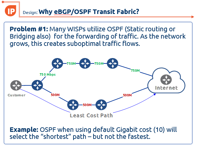
One of the latest designs I have been working on is using eBGP and an OSPF transit fabric to provide traffic engineering and load balancing. If you missed this presentation at the 2017 MikroTik User Meeting in Denver, CO, here are the slides:
WISP-Design-Using-eBGP-and-OSPF-TF-traffic-engineering-MUM-2017_KevinMyers-4-by-3
]]>Rough specs are:
- 6 slot chassis
- Dual redundant 720 Gbps CPU modules
- Dual power
- 96 ports of copper 1 gig
- 48 1 gig SFP ports
- 16 Ten gig SFP+ ports
Apparently this device will coincide with the release of RouterOS version 8 in 2026 [an inside source at MikroTik named “Janis” confirmed this is a realistic target date.]
Many covert mAP-quadcopters died to bring us this information…these photos are NOT for public distribution.
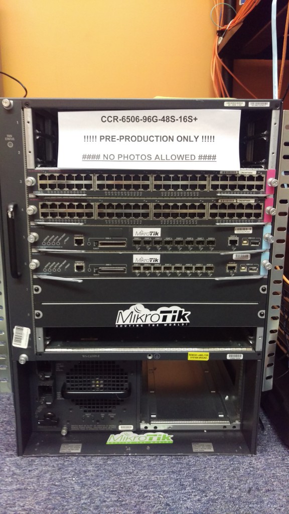
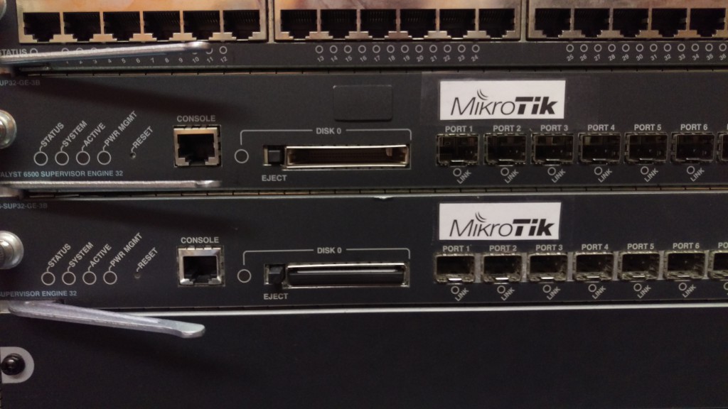
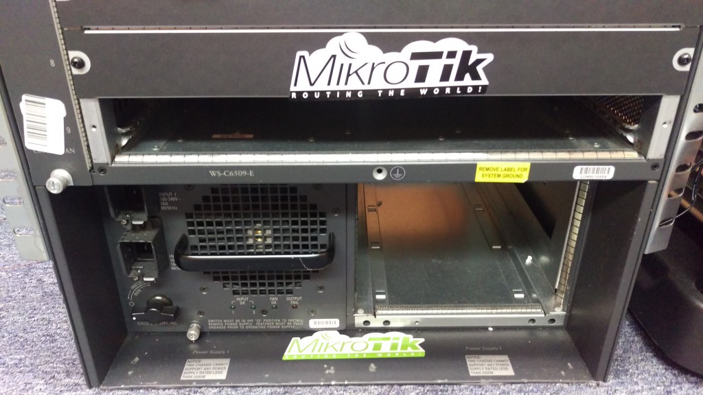
And if you haven’t quite figured it out yet…APRIL FOOLS DAY!!!! But seriously MikroTik….we need this router. 
]]>

Recently, I was fortunate enough to be invited by Brian Horn with WISPA.org to teach a session at WISP America 2016 in Lousiville, KY. We had the class on Tuesday, March 15th 2016 and the turnout and response were great. Many different people have asked for the presentation, so I decided to go ahead and post it here. Hope this helps some of you who are trying to get into MPLS and although it does have a bit of a WISP focus, almost all of the concepts in the presentation apply to wireline networks as well.
About the presentation
Scope: This session was 30 minutes long with a Q&A afterwards, so the material is really a deep dive on MPLS. The goal was to introduce WISP engineers and owners to MPLS and how it improves the network as well as revenue.
When should I put MPLS in my WISP or Service Provider network? The answer is ASAP! I was asked this question by a small WISP earlier in the week and he said i’m just too small to be thinking about MPLS. My response to him was simply – “Do you want to get MPLS in and working well when you only have a handful of routers or do you want to wait until you have a large number of routers and the cost/complexity of adding MPLS will increase significantly?”
Link to PDF version of the presentation:
ISP Architecture – MPLS Overvew, Design and Implemention for WISPs
]]>
Happy New Year and welcome to the VM you can punish your routers with
Hello from stubarea51.net and Happy New Year! We are back from the holidays and recharged with lots of new stuff in the world of network engineering. If you ever thought it would be cool to put a full BGP table into a lab router, GNS3 or other virtualized router, you’re not alone.
A while back, I tackled this post and got everything up and running:
http://evilrouters.net/2009/08/21/getting-bgp-routes-into-dynamips-with-video/
First of all, thanks to evilrouters.net for figuring out the hard parts so we could build this into a VM. After basking for a while in the high geek factor of this project, it gave me an idea to build a VM that could be distributed among network engineers and IT professionals. The idea is to easily spin up one or more full BGP tables to test a particular network design or convergence speed, playing with BGP attributes, etc. After a few months of tweaking it and getting the VM ready for distribution, we finally are ready to put it out for everyone to use.
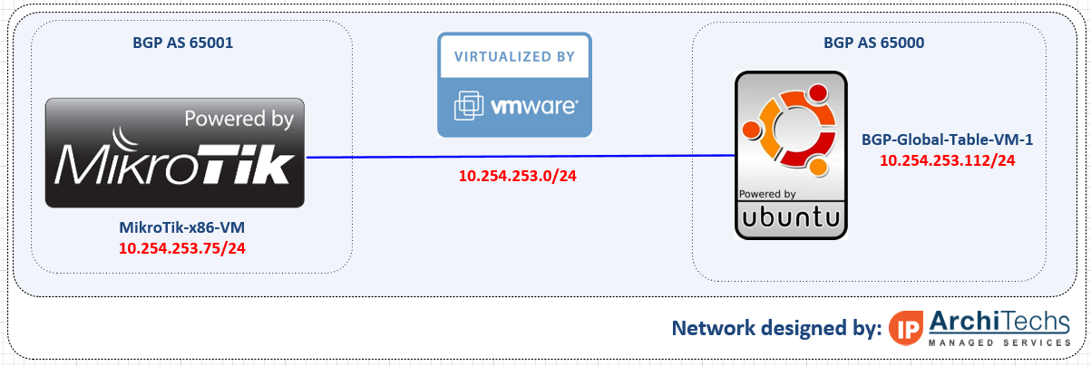
Network Diagram
Here is an overview of the topology we used for testing our full BGP table. This can be done a number of different ways and you can use just about any combination of Hypervisors including VM Ware and VirtualBox which are the two downloads included in this post. In this setup, we are using a MikroTik x86 VM to peer into the Ubuntu VM that has copies of the global table. It established an EBGP peering over 10.254.253.0/24 and takes in a full table.
Getting started
First you need to download either the VM Ware or VirtualBox OVA files and import them into your hypervisor. The setup and installation of VM Ware ESXi or VirtualBox is beyond the scope of this post, so please google it if you need help.
Downloads
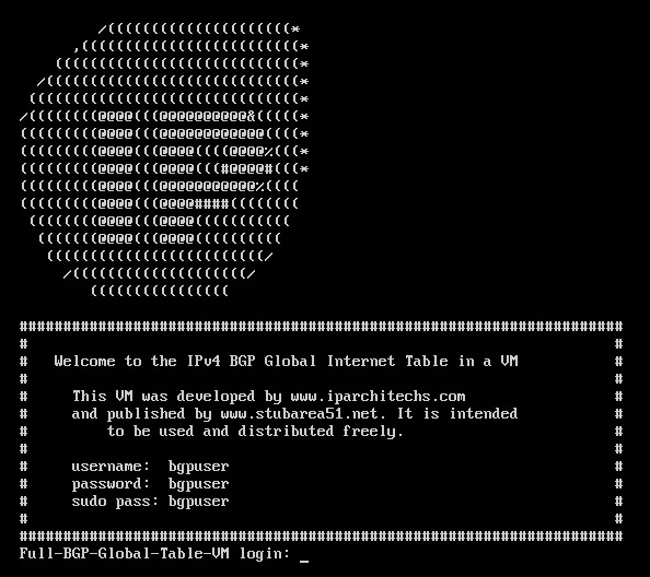
Powering up the VM
Once you have successfully imported the VM, you will get a screen that looks like this:
Credentials
Here are the credentials which you can change if needed.
username: bgpuser
password: bgpuser
sudo password: bgpuser
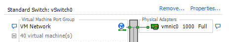
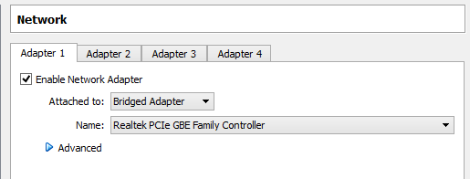
Bridging the VM NIC to your lab network
In order to have IP connectivity to another router (physical or virtual) you will need to setup the VM NIC to connect to the network you want to test on. There are a number of different ways to connect VMs into a virtual or physical network.
VM Ware – we connected the VM to the default VM management network (which is a physical server NIC) so it could reach other VMs and physical lab routers
VirtualBox – we bridged the VM to the NIC of the desktop we are running VirtualBox on so it could reach other VMs and physical lab routers
BGP Feeds that are used in this VM
The BGP feeds that are available come from the RIPE RIS Raw Data page and were archived in January 2016. We included 6 different tables from 4 continents so you can have up to 6 unique BGP tables to use in your lab testing. See the next section for the syntax to use for one of these files.
| RIPE RRC | File Name |
|---|---|
| rrc00.ripe.net | ISP1-Europe-Amsterdam-Jan-2016 |
| rrc01.ripe.net | ISP2-Europe-London-Jan-2016 |
| rrc06.ripe.net | ISP3-Asia-Tokyo-Jan-2016 |
| rrc15.ripe.net | ISP4-SouthAmerica-SaoPaulo-Jan-2016 |
| rrc11.ripe.net | ISP5-NorthAmerica-NewYork-Jan-2016 |
| rrc14.ripe.net | ISP6-NorthAmerica-PaloAlto-Jan-2016 |
Important Note !!!! – Using this VM does not provide connectivity to the Internet and will likely cause an outage when connected to a production network with live BGP peerings. This VM is intended to simulate an upstream peering for testing and lab development.
Setting up a BGP peering – BGP VM
Once you have IP connectivity and can ping the router you want to peer with, you can set up a peering on the VM. Here is the command syntax – first change to the bgp directory and issue the command below (with edits for your IPs and AS numbers)
bgpuser@Full-BGP-Global-Table-VM:~$ cd bgp
bgpuser@Full-BGP-Global-Table-VM:~/bgp$ sudo ./bgp_simple.pl -myas 65000 -myip 10.254.253.112 -peerip 10.254.253.75 -peeras 65051 -p ISP1-Europe-Amsterdam-Jan-2016
Options for the BGP Peering (using the program bgp_simple ver 0.12)
bgpuser@Full-BGP-Global-Table-VM:~/bgp$ ./bgp_simple.pl

Please provide -myas, -myip, -peerip and -peeras!

bgp_simple.pl: Simple BGP peering and route injection script.
Version v0.12, 22-Jan-2011.

usage:
bgp_simple.pl:
                -myas           ASNUMBER        # (mandatory) our AS number
                -myip           IP address      # (mandatory) our IP address to source the sesion from
                -peerip         IP address      # (mandatory) peer IP address
                -peeras         ASNUMBER        # (mandatory) peer AS number
                [-holdtime]     Seconds         # (optional) BGP hold time duration in seconds (default 60s)
                [-keepalive]    Seconds         # (optional) BGP KeepAlive timer duration in seconds (default 20s)
                [-nolisten]                     # (optional) dont listen at $myip, tcp/179
                [-v]                            # (optional) provide verbose output to STDOUT, use twice to get debugs
                [-p file]                       # (optional) prefixes to advertise (bgpdump formatted)
                [-o file]                       # (optional) write all sent and received UPDATE messages to file
                [-m number]                     # (optional) maximum number of prefixes to advertise
                [-n IP address]                 # (optional) next hop self, overrides original value
                [-l number]                     # (optional) set default value for LOCAL_PREF
                [-dry]                          # (optional) dry run; dont build adjacency, but check prefix file (requires -p)
                [-f KEY=REGEX]                  # (optional) filter on input prefixes (requires -p), repeat for multiple filters
                                                        KEY is one of the following attributes (CaSE insensitive):

                                                        NEIG            originating neighbor
                                                        NLRI            NLRI/prefix(es)
                                                        ASPT            AS_PATH
                                                        ORIG            ORIGIN
                                                        NXHP            NEXT_HOP
                                                        LOCP            LOCAL_PREF
                                                        MED             MULTI_EXIT_DISC
                                                        COMM            COMMUNITY
                                                        ATOM            ATOMIC_AGGREGATE
                                                        AGG             AGGREGATOR

                                                        REGEX is a perl regular expression to be expected in a
                                                        match statement (m/REGEX/)

Without any prefix file to import, only an adjacency is established and the received NLRIs, including their attributes, are logged.
Setting up a BGP peering – Your peering router
We used a MikroTik x86 VM in ESXi for this test, but any brand of virtual or physical router that supports BGP can be used.
[[email protected]] > routing bgp export
# jan/21/2016 10:34:43 by RouterOS 6.30.1
# software id = KC33-08AQ
#
/routing bgp instance
set default as=65001
/routing bgp peer
add hold-time=30m keepalive-time=4m15s name=BGP-VM remote-address=10.254.253.112 remote-as=65000 ttl=default
Sit back and watch hundreds of thousands of prefixes torture the CPU of your router

In the world of network engineering, learning a new syntax can challenging especially if you need a lot of detail quickly. The command structure for RouterOS can be a bit challenging sometimes if you are used to Cisco CLI commands. Most of us that have been in networking for a while got our start with Cisco gear and so it is helpful to draw comparisons between the commands, especially if you are trying to build a network with a MikroTik and Cisco router.
This is the first post in a series I’ve wanted to do for a while that creates a Rosetta stone essentially between IOS and RouterOS. We plan to tackle a number of other command comparisons like OSPF, MPLS and VLANs to make it easier for network engineers trained in Cisco IOS to successfully implement MikroTik / RouterOS devices. While many commands have almost the exact same information, others are as close as possible. Since there isn’t always an exact match, sometimes you may have to run two or three commands to get the information needed.
We plan to tackle a number of other command comparisons like OSPF, MPLS and VLANs to make it easier for network engineers trained in Cisco IOS to successfully implement Mikrotik / RouterOS devices.
Using GNS for testing
We used GNS3 to emulate both Cisco IOS and RouterOS so we could compare the different commands and ensure the translation was as close as possible.

BGP Commands
| Cisco Command | MikroTik Command |
|---|---|
| show ip bgp summary | routing bgp peer print brief |
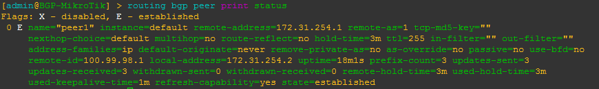
| show ip bgp neighbor | routing bgp peer print status |
| show ip bgp neighbor 1.1.1.1 advertised-routes | routing bgp advertisements print peer=peer_name |
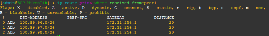
| show ip bgp neighbor 1.1.1.1 received-routes | ip route print where received-from=peer_name |
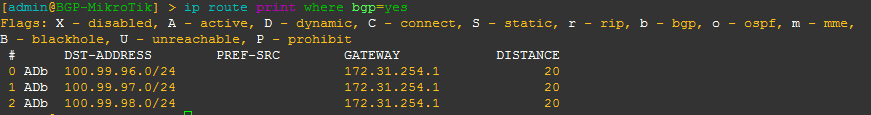
| show ip route bgp | ip route print where bgp=yes |
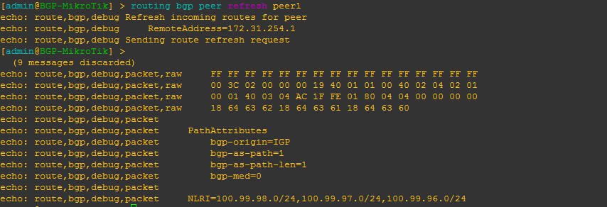
| clear ip bgp 172.31.254.2 soft in | routing bgp peer refresh peer1 |
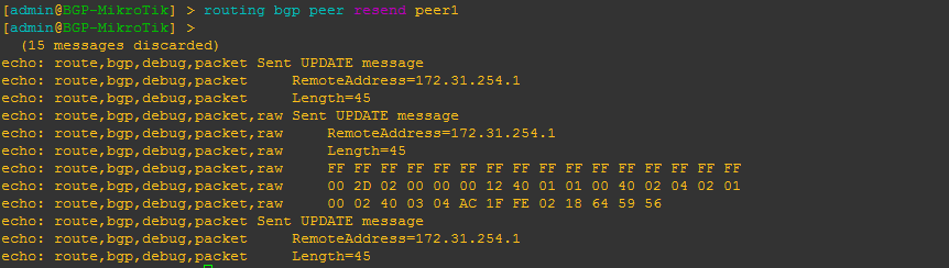
| clear ip bgp 172.31.254.2 soft out | routing bgp peer resend peer1 |
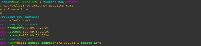
| BGP-Cisco(config)#router bgp 1 | /routing bgp instance set default as=2 |
| BGP-Cisco(config-router)#neighbor 172.31.254.2 remote-as 2 | /routing bgp peer add name=peer1 remote-address=172.31.254.1 remote-as=1 |
| BGP-Cisco(config-router)#network 100.99.98.0 mask 255.255.255.0 BGP-Cisco(config-router)#network 100.99.97.0 mask 255.255.255.0 BGP-Cisco(config-router)#network 100.99.96.0 mask 255.255.255.0 | /routing bgp network add network=100.89.88.0/24 add network=100.89.87.0/24 add network=100.89.86.0/24 |
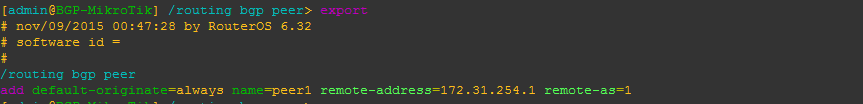
| BGP-Cisco(config)#router bgp 1 BGP-Cisco(config-router)#neighbor 172.31.254.2 default-originate | /routing bgp peer add default-originate=always name=peer1 remote-address=172.31.254.1 remote-as=1 |
Examples of the MikroTik RouterOS commands from the table above
[admin@BGP-MikroTik] > routing bgp peer print brief
This is a quick way to get a list of peers/AS and their status

[admin@BGP-MikroTik] > routing bgp peer print status
This is a command that will give you more detailed information about a BGP peer including MD5 auth, timers, prefixes received and the state of the peering as well as other info.
[admin@BGP-MikroTik] > routing bgp advertisements print peer=peer_name
This will allow you to see what BGP prefixes are actually being advertised to a peer and the nexthop that will be advertised

[admin@BGP-MikroTik] > ip route print where received-from=peer_name
This will allow you to see what BGP prefixes are actually being received from a peer and the nexthop that will be advertised
[admin@BGP-MikroTik] > ip route print where bgp=yes
This will allow you to see what all BGP prefixes that are in the routing table – both active and not. This is a slight difference between Cisco and MikroTik since Cisco keeps BGP routes that aren’t in the routing table in the bgp table, whereas MikroTik routers keep all routes in the routing table with a distinction between active and not.
[admin@BGP-MikroTik] > routing bgp peer refresh peer_name
This will allow you to force the BGP peer to resend all prefixes without tearing down the peering – similar to a soft clear in Cisco IOS.
[admin@BGP-MikroTik] > routing bgp peer resend peer_name
This will allow you to force RouterOS to resend all prefixes to the peer without tearing down the peering – similar to a soft clear in Cisco IOS.
Configure BGP instance and peering
Here is a very basic BGP peering config with the minimum required to get BGP running for RouterOS. It includes setting the BGP AS, a peering and several networks to advertise.
Originate a default route to a specific peer
This will configure the peering to originate or advertise a 0.0.0.0/0 route to the peer regardless of whether or not a default route already exists in the routing table. You can use the alternate default-originate=if-installed to only advertise a default route if one exists in the routing table.
More to come
There are so many commands to consider for BGP, we probably could have added close to 100, but we decided to list the commands we use the most often to start with and will be adding to the list of BGP commands as well as others like OSPF, MPLS and VLANs in future posts.
]]>
[adrotate banner=”5″]
Why we chose PPPoE as the next test
First of all, thanks to everyone for all the positive feedback, comments and questions about the CCR1072-1G-8S+ testing we have been posting in the last few months. Even MikroTik has taken an interest in this testing and we have gotten some great feedback from them as well.
We received more questions about the PPPoE capabilities of the CCR1072-1G-8S+ than any other type of request. Since we have already published the testing on BGP, throughput and EoIP, we have decided to tackle the PPPoE testing to understand where the limits of the CCR1072-1G-8S+ are. This is only a preview of the testing as we are working on different methods of testing and config, but this will at least give you a glimpse of what is possible.
30,000 PPPoE Connections !!!!
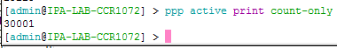
Overview of PPPoE connections and CPU load
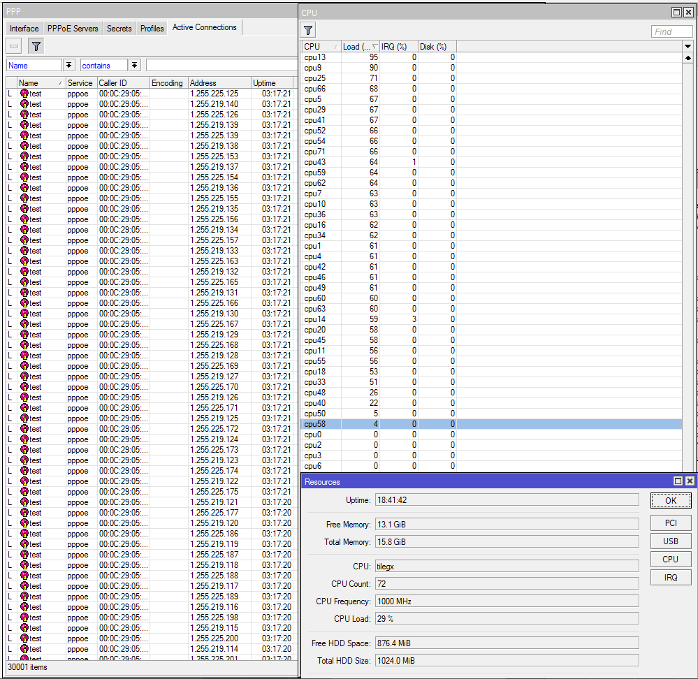
PRTG Monitoring
We have started using PRTG in the StubArea51.net lab as it makes monitoring of resource load over time much easier when we are testing. Check it out as it is free up to 100 sensors and works very well with MikroTik
https://www.paessler.com/prtg/download
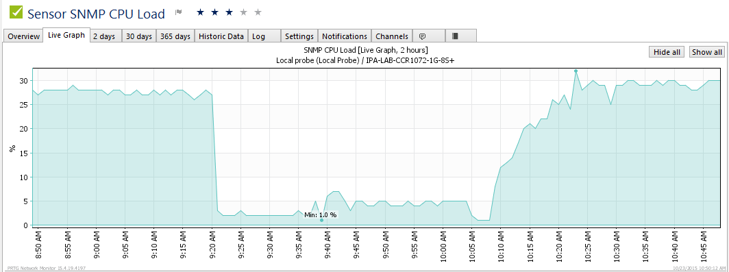
PRTG CPU Profile
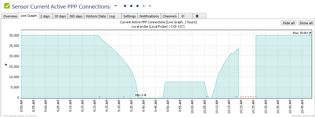
PRTG PPPoE connection count over time
It took us about 20 minutes to reach 30,000 connections…we are working on tuning the config to see if we can shorten the time it takes to build the connections. In the graph here, you can see it go form a 24 hour stable load of 30k connections donw to nothing as we prepare for a load test. At about 10:07 AM is when we started the full load test and you can see the time it takes to get to 30k.
More on the way!!!
This is just a small preview of our full PPPoE testing. We will be completing testing and should be publishing the results within the next week.
]]>[adrotate banner=”5″]
[metaslider id=282]
Getting to 10 Gbps using EoIP
The EoIP tunnel protocol is one of the more popular features we see deployed in MikroTik routers. It is useful anywhere a Layer 2 extension over a Layer 3 network is needed and can be done with very little effort / complexity. One of the questions that seems to come up on the forums frequently is how much traffic can an EoIP tunnel handle which is typically followed by questions about performance with IPSEC turned on. Answers given by MikroTik and others on forums.mikrotik.com typically fall into the 1 to 3 Gbps range with some hints that more is possible. We searched to see if anyone had done 10 Gbps over EoIP with or without IPSEC and came up empty handed. That prompted us to dive into the StubArea51 lab and set up a test network so we could get some hard data and definitive answers.
The EoIP protocol and recent enhancements
Ethernet over IP or EoIP is a protocol that started as an IETF draft somewhere around 2002 and MikroTik developed a proprietary implementation of it that has been in RouterOS for quite a while. Similar to EoMPLS or Cisco’s OTV, it faciltates the encapsulation of Layer 2 traffic over a Layer 3 network such as the Internet or even a private L3 WAN like an MPLS cloud. If you follow MikroTik and RouterOS updates closely, you might have come across a new feature that was released in version 6.30 of RouterOS.
What's new in 6.30 (2015-Jul-08 09:07):

*) tunnels - eoip, eoipv6, gre,gre6, ipip, ipipv6, 6to4 tunnels
   have new property - ipsec-secret - for easy setup of ipsec
   encryption and authentication;
This is a much anticipated feature as it simplifies the deployment of secure tunnels immensely. It makes things so easy, that it really gives MikroTik a significant competitive advantage against Cisco and other vendors that have tunneling features in their routers and firewalls. When you look at the complexity involved in deploying a tunnel over ipsec in a Cisco router vs. a MikroTik router, there is a clear advantage to using MikroTik for tunneling. I originally looked into this feature for EoIP but it is available many other tunnel types like gre, ipip and 6to4.
When you look at the complexity involved in deploying a tunnel over ipsec in a Cisco router vs. a MikroTik router, there is a clear advantage to using MikroTik for tunneling.
Here is one of the simpler implementations of L2TPv3 over IPSEC in a Cisco router which still has a fair amount of complexity surrounding it.
http://www.cisco.com/c/en/us/support/docs/security/flexvpn/116207-configure-l2tpv3-00.html
VS.
http://wiki.mikrotik.com/wiki/Manual:Interface/EoIP
The MikroTik config has 3 required config items for EoIP on each router vs double the steps with Cisco and the added complexity of troubleshooting IPSEC if you get a line of config wrong.
The test network
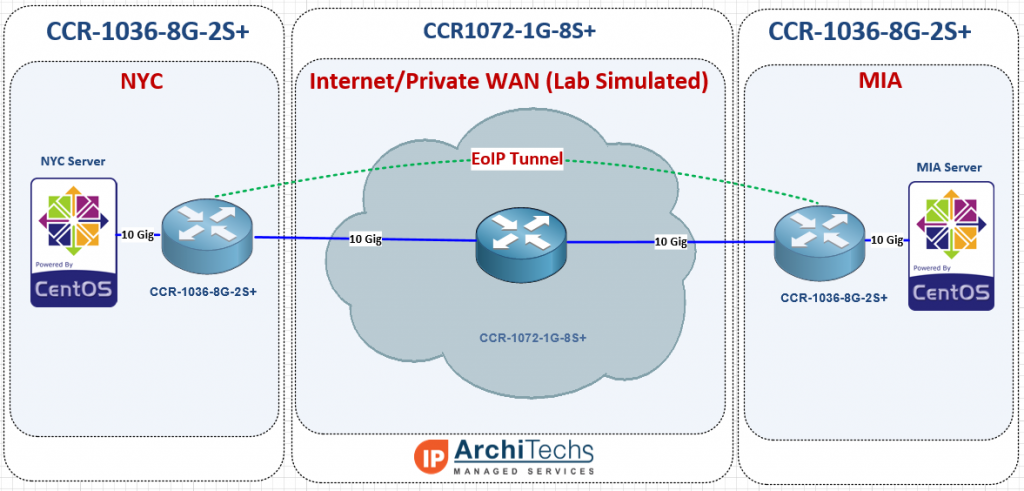
In order to test 10 Gbps speed over EoIP, we needed a 10 Gbps capable test network and decided to use two CCR-10368G-2S+ as our endpoints and a CCR1072-1G-8S+ as the core WAN. We used an HP DL360-G6 with ESXi as the hypervisor to launch our test VMs for TCP throughput. We typically use VMs instead of MikroTik’s built in bandwidth tester because they can generate more traffic and have more granularity to stage specific test conditions (TCP window, RX/TX buffer, etc).
Concept of testing
Most often, EoIP is implemented over the Internet and so using 9000 as a test MTU might be surprising to some users and possibly irrelevant, but when using a private WAN, quite often a Layer 3 solution is much less expensive than Layer 2 handoffs (especially at 10 Gbps) and 9000 bytes is almost always supported on that kind of transport, so L2 over private L3 definitely has a place as a possible application for EoIP with 9000 byte frames.
9000 byte MTU unencrypted
9000 byte MTU encrypted with IPSEC
1500 byte MTU unencrypted
1500 byte MTU encrypted with IPSEC
And the results are in!!! 10 Gbps is possible over EoIP
10 Gbps over EoIP (Unencrypted with 9000 byte MTU)
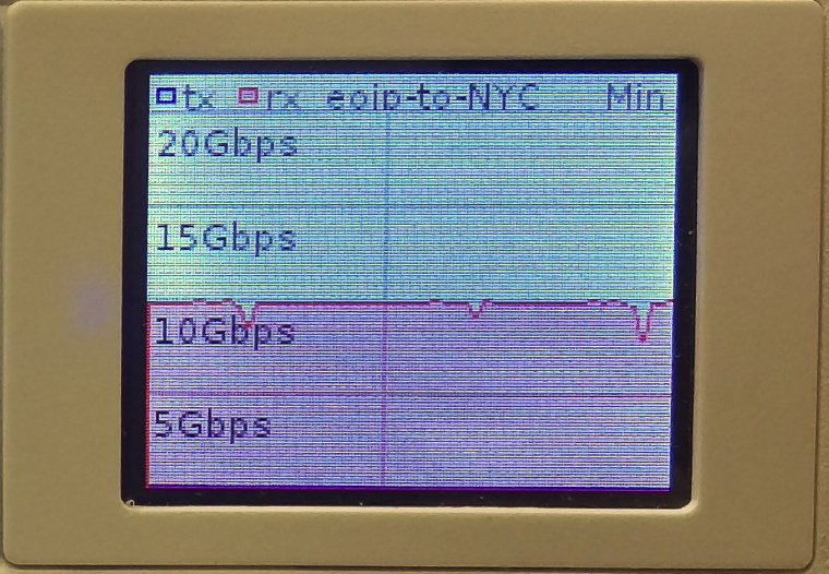
Video of 10 Gbps over EoIP (Unencrypted with 9000 byte MTU)
7.5 Gbps over EoIP (IPSEC encrypted with 9000 byte MTU)
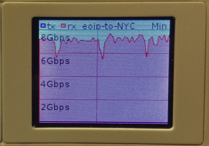
Video of 7.5 Gbps over EoIP (IPSEC encrypted with 9000 byte MTU)
6.4 Gbps over EoIP (Unencrypted with 1500 byte MTU)
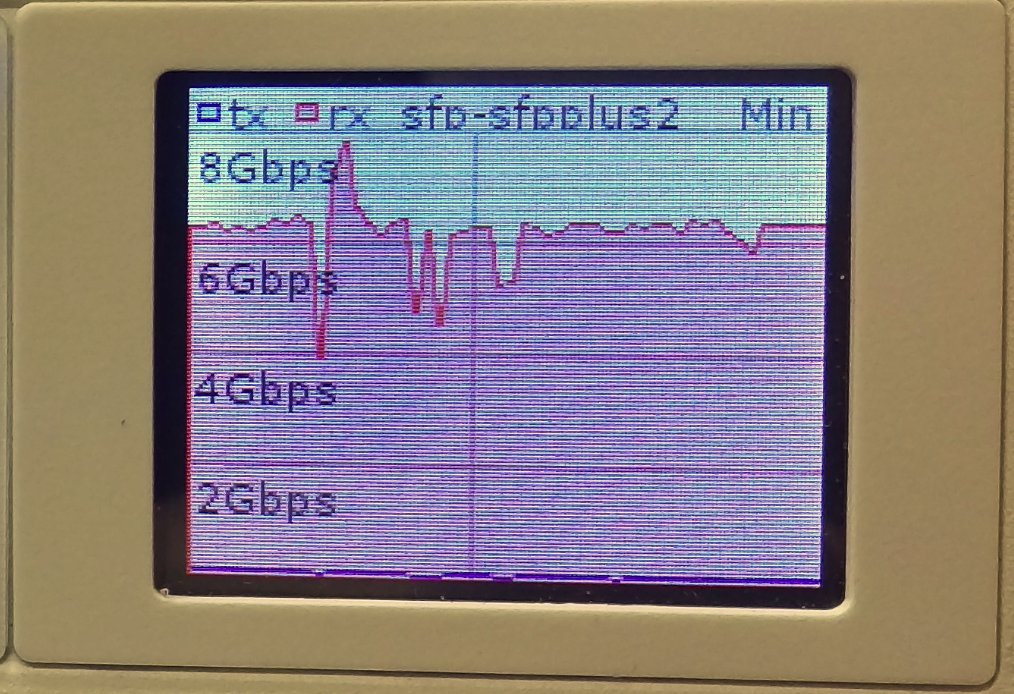
Video of 6.4 Gbps over EoIP (Unencrypted with 1500 byte MTU)
1.7 Gbps over EoIP (IPSEC encrypted with 1500 byte MTU)
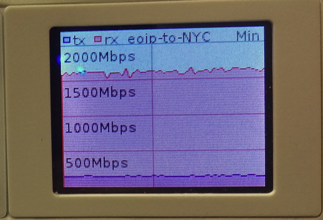
Video of 1.7 Gbps over EoIP (IPSEC encrypted with 1500 byte MTU)
Video will be posted soon.
Use cases and conclusions
The CCR1036 certainly had no issues getting to 10 Gbps with the right MTU and test hardware, but we were suprised that the IPSEC thoughput was so high. Considering a pair of CCR1036-8G-2S+ routers are just a little over $2000.00 USD, 7.5 Gigabits of encrypted throughput with IPSEC is incredible. Even over a 1500 byte MTU, the 1.7 Gbps we were able to hit is amazing considering it would probably take at least 20k to 30k USD to reach that kind of encrypted throughput with equipment from a mainstream network vendor like Cisco or Juniper.
Use cases for this are probably too numerous to mention but we came up with a few
- Extending an ISP or joining two or more ISPs in different regions
- High volume PPPoE backhaul to a BRAS
- Data Center Interconnect (DCI) at Layer 2
- Enterprise HQ and Branch connectivity or backup
- Layer 2 network extension for network migration or merger.
Please feel free to leave comments with questions about the testing or use cases we might not have thought of…we love getting feedback
[metaslider id=249]
The 80 Gbps barrier has finally been broken (and yes we are rounding up) !!!!
Well at least it has been reached by someone other than MikroTik. It’s taken us quite a while to get all the right pieces to push 80 Gbps of traffic through the CC1072 but with the latest round of servers that just got delivered to our lab, we were able to go beyond our previous high water mark of 54 Gbps all the way to just under 80 Gbps. There have been a number of questions about this particular router and what the performance will look like in the real world. While this is still a lab test, we are using non-MikroTik equipment and iperf which is considered an extremely accurate performance measuring tool for TCP and UDP.
Video of the CCR1072-1G-8S+ in action (Turn up your volume to hear the roar of the ESXi servers as they approach 80 Gbps)
How we did it – The Hardware
CCR1072-1G-8S+ – Obviously you can’t have a test of the CCR1072 without one to test on. Our CCR1072-1G-8S+ is a pre-production model so there are some minor differences between it and the units that are shipping right now.
HP DL360-G6 – It’s hard to find a better value in the used server market than the HP DL360 series. This series of server can be found on ebay for under $500 USD in general and makes a great ESXi host for development and testing work.
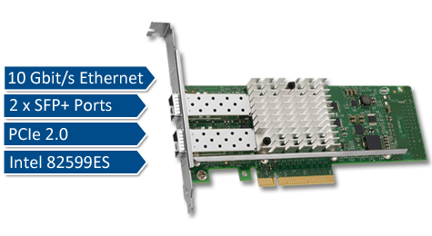
Intel x520-DA2 10 Gbps PCI-E NIC – This NIC was definitely not the cheapest 10 gig NIC on the market, but after some research, we found it was one of the most compatible and stable across a wide variety of x86 hardware. The only downside to using this particular NIC is the requirement to use INTEL branded SPF+ modules. We tried several types of generics and after reading some forums posts, we were able to figure out that it only takes a few different types of INTEL SFP+ modules. This didn’t impact performance in any way but doubled the cost of the SFPs required.
How we did it – The Software
RouterOS – We tried several thoughought the testing cycle, but settled on 6.30.4 bugfix.
iperf3 – If you need to generate traffic for a load test, this is probably one of the best programs to use.
VM Ware ESXi 6.0 – There were certainly a fair amount of hypervisors to choose from, and we even considered a Docker deployment for the performance advantages but in the end, VM Ware was the easiest to deploy and manage since we needed some flexibility in the vswitch and 9000 MTU.
CentOS 6.6 Virtual Machines – We chose CentOS as the base OS for TCP throughput testing because it supports VM Ware tools and the VMXNET3 paravirtualized NIC. It is not possible to get a VM to 10 Gbps of throughput without using a paravirtualized NIC so this limits the range of Linux distros to mainstream types like Ubuntu and CentOS. Also, we tend to use CentOS more than the other flavors of linux and so it allowed us to get the VMs ready quickly to generate traffic.

Network Topology for the test – We essentially had to put two VLANs on every physical interface so that the link could be fully loaded by using the 1072 to route between VLANs. A VM was built on each VLAN and tagged in the vswitch for simplicity. In earlier tests, we tried to use LACP between ESXi and the 1072 but had problems loading the links fully with the hashing algorithms we had available.
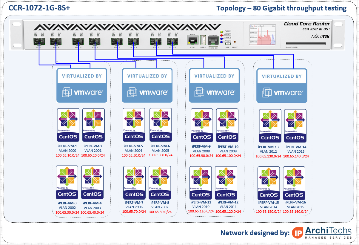
RouterOS Config for the test
www.iparchitechs.com/iparchitechs.com-ccr1072-80gig-test-config.rsc
Conclusions, challenges and what we learned
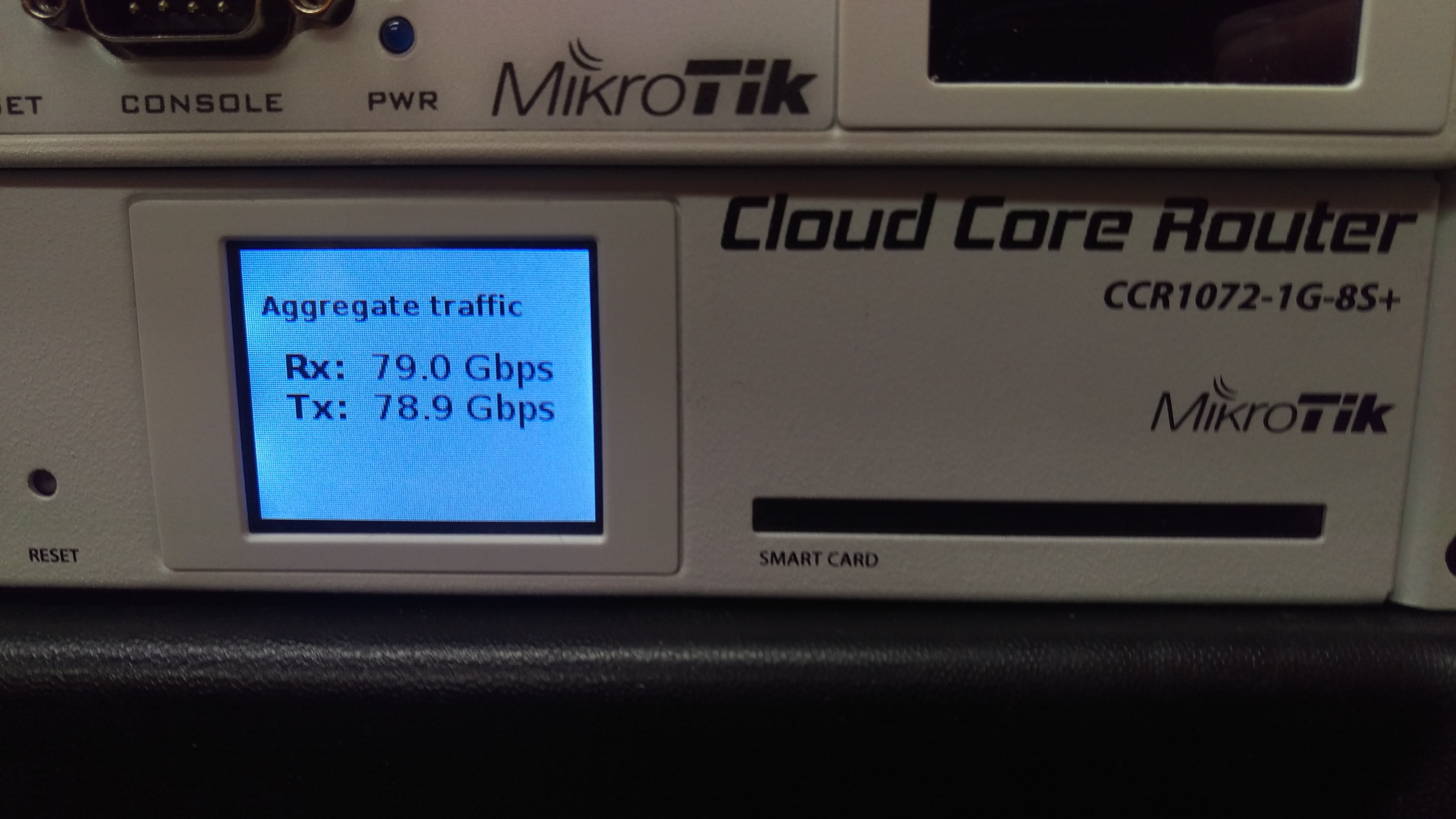
The CCR1072-1G-8S+ is an extremely powerful router and had little difficulty in reaching full throughput once we were able to muster enough resources to load all of the links. As RouterOS continues to develop and moves into version 7, this router has the potential to be extremely disruptive to mainstream network vendors. At $3,000.00 USD list price, this router is ab absolute steal for the performance, 1U footprint and power consumption. Look for more and more of these to show up in data centers, ISPs and enterprises.
Challenges
There have been a number of things that we have had to work through to get to 80 Gbps but we finally got there.
- VMWARE ESXi – LACP Hashing – Initially we built LACP channels between the ESXi hosts and the 1072 expecting to load the links by using multiple source and destination IPs but we ran into issues with traffic getting stuck on one side of the LACP channel and had to move to independent links.
- Paravirtualized NIC – The VM guest OS must support a paravirtualized NIC like VMXNET3 to reach 10 Gbps speeds.
- CPU Resources – TCP consumes an enormous amount of CPU cycles and we were only able to get 27 Gbps per ESXi host (we had two) and 54 Gbps total
- TCP Offload – Most NICs these days allow for offloading of TCP segmentation by hardware in the NIC rather than the CPU, we were never able to get this working properly in VM WARE to reduce the load on the hypervisor host CPUs.
- MTU – While the CCR1072 supports 10,226 bytes max MTU, VMWARE vswitch only supports 9000 so we lost some potential throughput by having to lower the MTU by more than 10%
What we learned
- MTU – In order for the CCR1072-1G-8S+ (and really any MikroTik) to reach maximum throughput, the highest L2/L3 MTU (we used 9000) must be used on:
- The CCR
- The Guest OS
- The Hypervisor VSWITCH
- Hypervisor Throughput – Although virtualization has come a long way, there is still a fair amount of performance lost especially in the network stack when putting a software layer between the Guest OS and the Hardware NIC.
- CPU Utilization with no firewall rules or queues is very low. We haven’t had a chance to test with queues or firewall rules but CPU utilization never went above 10% across all cores.
- TCP tuning for 10 Gbps in the Guest OS is very important – see this link: https://fasterdata.es.net/host-tuning/linux/
Please comment and let us know what CCR1072-1G-8S+ test you would like to see next!!!
]]>[adrotate banner=”4″]
Breaking the 80 Gbps barrier!!!

The long wait for real-world 1072 performance numbers is almost over – the last two VMWARE server chassis we needed to push the full 80 Gpbs arrived in the StubArea51 lab today. Thanks to everyone who wrote in and commented on the first two reviews we did on the CCR-1072-1G-8S+. We initially began work on performance testing throughput for the CCR1072 in late July of this year, but had to order a lot of parts to get enough 10 Gig PCIe cards, SFP+ modules and fiber to be able to push 80 Gbps of traffic through this router.
Challenges
There have been a number of things that we have had to work through to get to 80 Gbps but we are very close. This will be detailed in the full review we plan to release next week but here are a few.
- VMWARE ESXi – LACP Hashing – Initially we built LACP channels between the ESXi hosts and the 1072 expecting to load the links by using multiple source and destination IPs but we ran into issues with traffic getting stuck on one side of the LACP channel and had to move to independent links.
- CPU Resources – TCP consumes an enormous amount of CPU cycles and we were only able to get 27 Gbps per ESXi host (we had two) and 54 Gbps total
- TCP Offload – Most NICs these days allow for offloading of TCP segmentation by hardware in the NIC rather than the CPU, we were never able to get this working properly in VM WARE to reduce the load on the hypervisor host CPUs.
- MTU – While the CCR1072 supports 10,226 bytes max MTU, VMWARE vswitch only supports 9000 so we lost some potential throughput by having to lower the MTU by more than 10%
Results preview
Here is a snapshot of where we have been able to get to using 6.30.4 bugfix so far
Single TCP Stream performance at 10 Gig in iperf at 9000 bytes MTU (L2/L3)
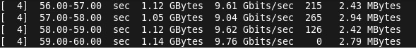
Throughput in WinBox

Max throughput so far with two ESXi 6.0 hosts (HP DL360 G6 with 2 Intel Xeon x5570 CPUs)
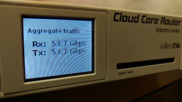
Two more servers arrived today – Full results coming very soon!
Once we hit the performance limit at 54 Gbps, we ordered two more servers and they just arrived. We will be racking them into the lab immediately and should have some results by next week. Thanks for being patient and check back soon!!
]]>
[adrotate banner=”4″]
As we all patiently await the release of RouterOS (RoS) v7 beta, MikroTik has announced a change in the way RoS development is organized. There will now be three different tracks of development:
Bugfix only – When a current build is released, only fixes to known bugs will be added to this branch of development
Current – Current release will contain bugfixes and new features
Release Candidate – The release candidate will remain the development build for the next “current” release.
Graphical Overview of the new development cycle
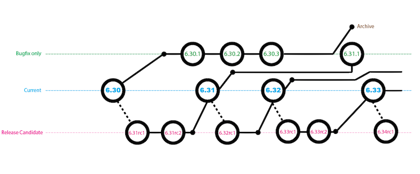
Image and notes below are from here
A small addendum: the Bugfix only will only contain verified fixes, and no new features. The Current release contains the same fixes but also new features and other improvements, sometimes also less critical fixes than in Bugfix. And finally the Release Candidate is more likely to a nightly build. We will not to intensive testing before publishing these, only quick check if upgrade can be done and if most features work fine.
Origin
The idea originally came out of this thread and after a flurry of positive commentary, it became a working practice shortly therafter.
We plan to make sub-version releases that only contain fixes and no new features.
For example, we would release 6.30 with some new features in FastPath. Then, if some issues are found, we would make 6.30.1 with only fixes and no new functionality. When we add a new option or feature, we would make 6.31.
6.XX.Y – only bug fixes
6.XX – fixes and feature changesWe could even make several fix-only releases in a row, if needed.
The idea is that you can upgrade to a sub-point release without risking new bugs, that could come with new features being added.
As the v6 cycle is coming to an end, there is simply no other ‘branch’ to put new features in, as v7 is still too ‘raw’. We could stop with the sub-point releases once v7 is mature enough for general use.
MikroTik download page gets a slight refresh with a new drop down
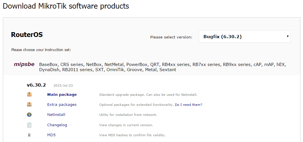
Thoughts
This a very positive change for MikroTik and will go a long way with customers and integrators to be able to select code based on the needs of the environment. This release cycle is very similar to other network vendors (Think of Cisco IOS General Deployment vs Maintenance Deployment) and works well.
Code selection is such a critical element to the stability of a network and it’s helpful to have the ability to load a RoS code that has been patched but without new features. It’s a bit early to tell as to how much of an impact this will make in the MikroTik community, but the results so far look promising. I’ve done upgrades on a number of CCRs and 2011 series routers from 6.30 –> 6.30.1 –> 6.30.2 bugfix only and haven’t seen any major stability issue s or other bugs when running on a BGP/MPLS/OSPF service provider network.
There was a lot of churn with bugs and working features breaking early on in 6.x and this change should help to avoid at least some of that upheaval when 7.x makes it to a “current” release.
]]>
Here is Part 1 of the CCR1072-1G-8S+ review in case you missed it!
CCR1072-1G-8S+ Ultimate BGP Performance test
After many days of testing, Part 2 is finally here! Welcome to the stubarea51.net BGP gauntlet. We subjected the CCR1072 to different types of network torture stress testing. Continuing on from our initial review, we chose BGP as the first way to test the limits and capacity of the CCR1072-1G-8S+.
Here is an overview of our lab environment to test the new CCR
- CCR1072-1G-8S+
- CCR1009-8G-1S-1S+
- CRS-125-24G-1S+
- x86 VMs on ESXi 6.0 for upstream BGP peering
- (2) ESXi 6.0 Hosts with 20 Gb (4×10) connectivity
- Multimode 10 gig SFP+ using 50/125 OM3 fiber
All RouterOS devices were loaded with the latest stable code (6.30.1 at the time of testing)
Network Design of the StubArea51 LAB setup for BGP testing
For this series of testing, we took our two ESXi 6.0 hosts and built a number of VMs using RouterOS and Ubuntu to supply the 1.21 Gigawatts 3.6 Million routes we would need to beat up on the CCR1072 for a few days. If you’re not familiar with the RIPE Routing Information Service (RIS) project, go here to take a look at the routing tables we used. Because the route server does not load routes nearly as quickly as a router, we used a CCR-1009-1S-1S+ to take in a single copy of the 457,461 routes in the Palo Alto IX public BGP table (July 2015). Then we set up eBGP peerings between the CCR1009 and each of the 8 BGP upstream VMs to give the CCR1072 plenty of peers. We also put two iBGP VMs in the same AS as the 1072 so we could test the route reflection capabilites of the CCR1072.
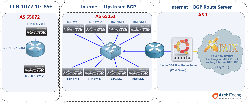
Concept of Testing in v6.30.1
One of the first things we wanted to test on the CCR-1072-1G-8S+ was how quickly it handled large BGP routing tables. It is probably a good idea to take a slight detour here and mention that in version 6 of RouterOS, the BGP process is not multi-threaded, so it is limited to one core. As such, there are improvements MikroTik is working on to make pulling in large BGP tables faster and more efficient. Here is that discussion in the MikroTik forums:
http://forum.mikrotik.com/viewtopic.php?t=69931
Next generation of code – RouterOS v7
After exhibiting and presenting at the USA MUM 2015 in Miami, we had a lot of time to talk to MikroTik and get some insight on what is happening with optimizing BGP in RouterOS. MikroTik has seen major BGP performance improvements in v7. I seem to remember a slide that was presented at the MUM with some specific performance numbers on v7 but I couldn’t find it. I did come across a slide from the 2014 MUM in Russia that talks about the routing improvements in v7:
This presentation on CCR Tips and Tricks by Janis Megis from that MUM is available here
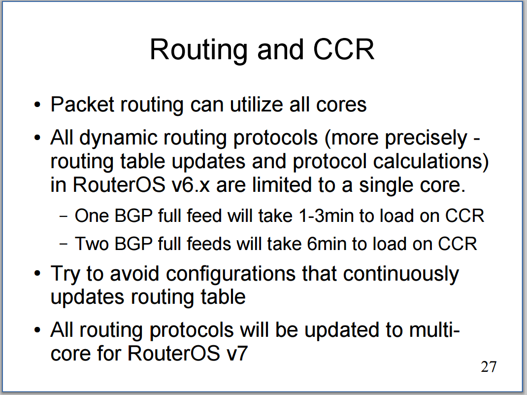
Testing Results
Here are the results of the BGP testing we have done that list:
- How many peers are used
- How many total routes are taken in
- How long it took to fully converge
- VRF performance results (if applicable)
- Route-reflection performance results (if applicable)
Public BGP Table – IPv4 with 1 upstream peer (457,461 routes – 1 Minute 33 seconds)
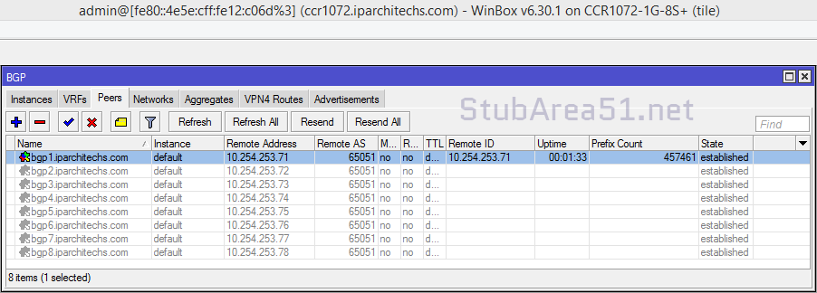
Public BGP Table – IPv4 with 2 upstream peers (914,922 routes – 3 Minutes 25 seconds)
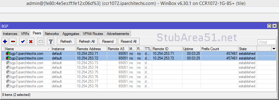
Public BGP Table – IPv4 with 4 upstream peers (1,829,844 routes – 7 Minutes 8 seconds)
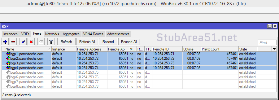
Public BGP Table – IPv4 with 8 upstream peers (3,659,688 routes – 13 Minute 17 seconds)
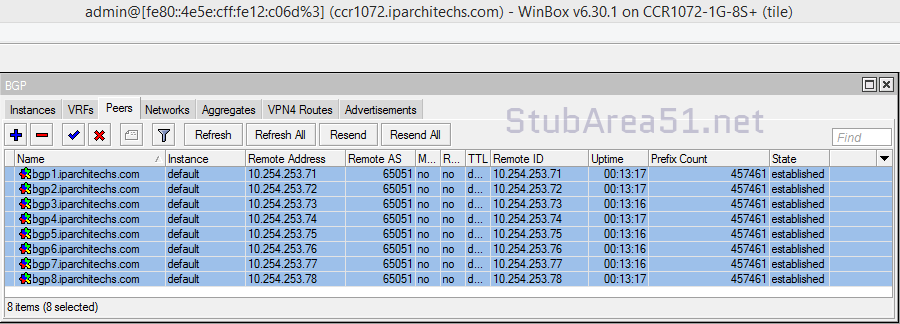
Public BGP Table – IPv6
Unfortunately, we did not have a way to test a full IPv6 BGP table in our lab. We are working on enabling that for future testing and will update once we have some results.
BGP Performance in a VRF – IPv4 with 8 upstream peers (3,659,688 routes – 15 Minutes 45 seconds)
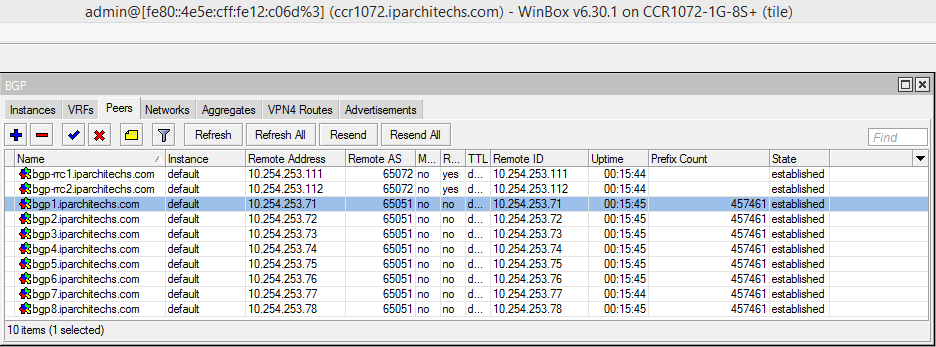
BGP Route Reflection – 2 clients (914,922 routes sent – 1 Minute 53 seconds)
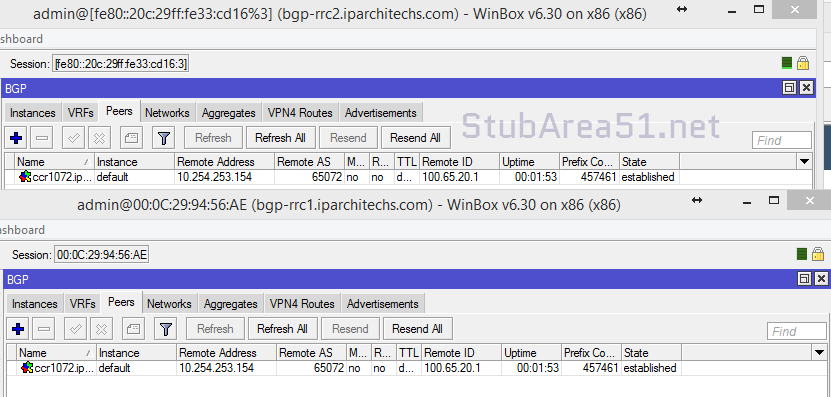
Conclusion
The CCR-1072-1G-8S+ is a fantastic BGP core or edge router. It is able to take in a full table in just over a minute, and is able to take in two tables (which is the most common type of BGP peering deployment we see) in just over 3 minutes, which puts on equal or better footing with a Cisco ASR 1001/1002 at a fraction of the cost.
We see the CCR-1072-1G-8S+ as an extremely strong candidate to use as an Internet BGP edge or core router. A pair of the 1072 routers would also make great WAN aggregation routers for an enterprise data center. Considering most large enterprises don’t go much beyond 10,000 to 15,000 BGP routes in their private MPLS routing tables, the CCR1072 would be able to converge almost immediately and provide stable and scalable throughput to the core.
The next phase of testing we will move into involves throughput testing using iperf on the 1072 with 20 gbps, 40 Gbps and 80 Gbps load tests – we will use BGP/OSPF and MPLS/VPLS configurations to look at performance differences for different types of networks.
CCR-1072-1G-8S+ available soon @
![]()
http://www.roc-noc.com/mikrotik/routerboard/CCR1072-1G-8Splus.html
Stay Tuned!
Coming next – MikroTik CCR1072-1G-8S+ Review (Part 3 ) 20 Gpbs, 40Gbps and 80 Gbps routing performance testing over BGP/OSPF/MPLS.
]]>It has been a busy week and we have been working hard on CCR1072 testing. The full review for BGP Performance is still a few days away, but here is a sneak preview of some of the testing in the stubarea51 Lab.
We put just under 1.7 Million routes across 4 BGP peers into the CCR1072-1G-8S+ and it was fully converged in 2 Minutes and 42 seconds.
Here is a screen shot of the CCR1072-1G-8S+ after converging with 4 full feeds.
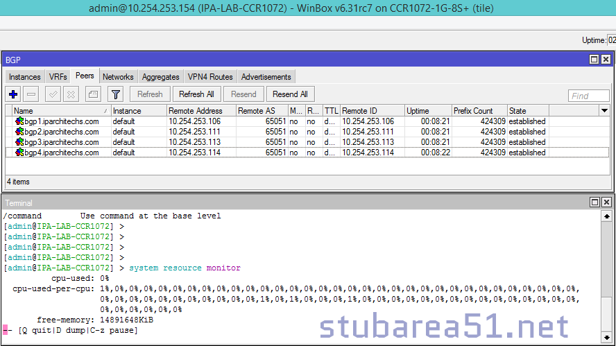
07/25/2015 – Thanks to Normunds @ MikroTik for sending over photos of the production CCR-1072-1G-8S+ which have now been included in the slideshow
[metaslider id=52]
CCR-1072-1G-8S+ available soon @
![]()
http://www.roc-noc.com/mikrotik/routerboard/CCR1072-1G-8Splus.html
UPDATE 7/10/2015 – MikroTik officially lists the CCR1072
http://routerboard.com/CCR1072-1G-8Splus
NOTE: The pictures in this review are of a pre-production CCR1072. The CCR1072 that is shipping has some minor differences on the mainboard and the case. MikroTik is sending updated pictures and we will post those as soon as they come in!
StubArea51.net prepares for CCR1072 performance testing in the Flowood, MS lab
Well, the long wait is finally over. According to Tom over at www.roc-noc.com, the CCR1072 will start shipping in the next 2 weeks and we will be adding it to our development lab in Flowood, MS. We were fortunate enough to get a significant amount of time with the new flagship router down in Miami at the 2015 USA MUM thanks to MT. The arrival of the CCR1072 and 80 Gbps of throughput opens up new doors for MikroTik. The CCR1072 positions MikroTik to break into larger markets and enables competition against industry players like Cisco and Juniper.
This review will be divided into three separate posts (this is Part 1):
- Hardware/Specs
- Throughput testing/performance
- BGP peer load testing.
The first section will focus on the design, hardware specifications and use cases. We will have a CCR1072 in the Stub Area 51 lab very shortly and will be connecting it to our 10 Gbps capable ESXi servers to provide TCP/UDP performance metrics on IPv4 and IPv6. We will also be testing the BGP Peering capability of the CCR1072 by connecting it to our service provider lab and sending multiple full feeds simultaneously to see how it handles the load.
Raw Specs and product description
Let’s take a look at the numbers and product description from MikroTik:
CCR1072-1G-8S+ is an industrial grade super fast router with cutting edge 72 core CPU. If you need many millions of packets per second – Cloud Core Router is your best choice.
- 72 core networking CPU, 1 GHz clock per core
- 16GB ECC RAM
- State of the art TILE GX architecture
- 8x SFP+ ports for 10 Gigabit connectivity
- Ports directly connected to CPU
- Up to 80 Gbps throughput
- Over 100 million pps packet throughput
- 1U rackmount case
- Color touchscreen LCD display
- Two hot-swap power supplies for redundancy
- MicroSD and 2x USB
- Two M.2 slots accept 800mm Key-M x4 PCIe 2.0 modules
Under the hood
With the air channel installed for the quad fan assembly

With the air channel removed and the looking at the CPU heat sink
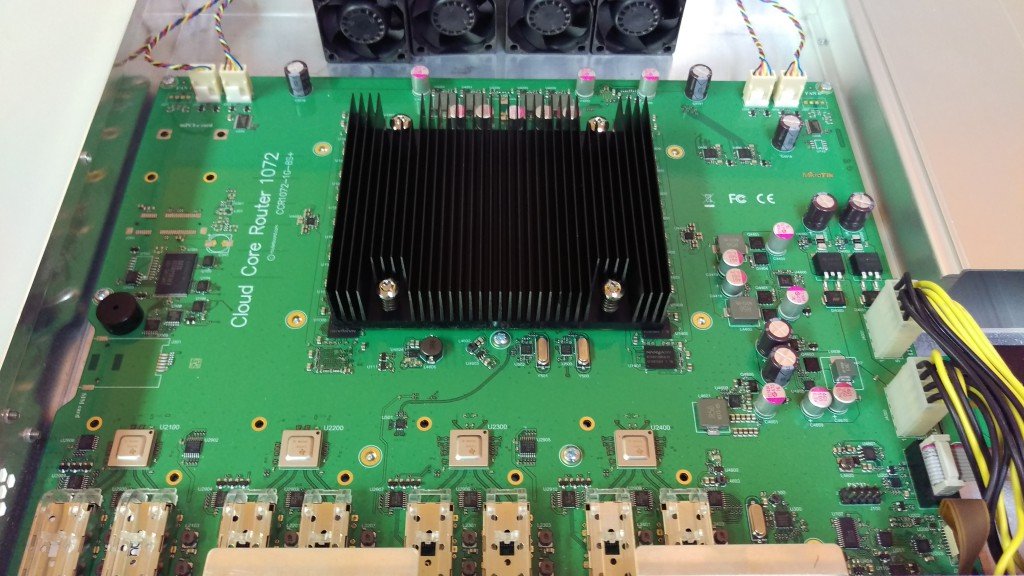
Power redundancy
One trend that I hope MikroTik continues across the rack mount product line is the option of dual power supplies like on the CCR1009. This has been a long awaited feature on MikroTik routers and it helps to position MikroTik into segments it has struggled to gain a foothold on like enterprise and data center networking.


72 Cores for 80Gbps+ worth of Interwebs!
A look inside the heart of the beast at the 72 Core Tilera gx8072 processor.

Mikrotik’s published speed numbers for the CCR1072 are 80 Gbps, but if you read the Tilera specs, it is capable of 100 Gbps of throughput. The 80 Gbps rating appears to come from the 8 x 10 Gig interfaces connected to the mPIPE. It would be interesting to see if any more 10 gig interfaces could be added via the PCIe slots.
Source: http://www.tilera.com/products/?ezchip=585&spage=618

Use Cases
- Service Provider – A number of ideas come to mind for ISPs – This could be used in the core / distribution with BGP/OSPF/MPLS, although it may not be the most efficient router to use to terminate public BGP until the router can process the tables more quickly. This would also make a great PE for a larger MPLS network that needs more resources on the PE. We will be testing the CCR1072 with multiple full feeds to see how well it handles them.
- Data Center – This could easily be the Layer 3 core of even a medium size data center and certainly those renting a partial rack of COLO space. InterVLAN routing at 80 Gbps easily exceeds the needs of all but the big data operators. These could also be used for throughput to IP based storage like NFS or iSCSI. There is a trend in Data Center design towards moving dynamic routing down to the end host and the 1072 could be positioned as a TOR (Top of Rack) or EOR (End of Row) L3 routing point.
- High throughput L4-L7 Firewall – When used as a firewall deployed at Layer 2 or 3, this router can move a large amount of data through its stateful firewall. Considering the Cisco 5585x starts at 20 gig of throughput and is typically approaching $100,000 to deploy, this could be a game changer in the firewall world at just under $3K per box.
- High Performance IPv4 / IPv6 Proxy / Web Cache – The SD slot opens up some great possibilities to build a high performance web proxy with caching. Throw in some Layer7 rules and you have a very economical IPv4 / IPv6 dual stack capable proxy capable of pushing traffic way beyond the capacity of most Internet pipes.
- Enterprise – When coupled with the right 10 gig switch, the CCR1072 is well suited to run an Enterprise campus and handle converged Data, Voice and Video. The 1072 is ideal for a core or distribution layer in the Enterprise.
Design Example – Data Center CCR1072 implementation
This is a design adapted from an initial Data Center buildout we labbed and presented at the US 2014 MUM on achieving HA and high throughput with a CCR 1036-8G-2S+ as the Layer 3 core in a Data Center. We have taken and adapted many of the design principles of that network and updated the design with the CCR1072.
See presentation slide here in PDF format: Mikrotik-Data-Center-MUM-2014_KevinMyers-4-by-3
Video is below:
The original design was built using CCR1036-8G-2S+ and used 20 Gig LACP channels to achieve 40 Gbps of aggregate throughput using ECMP with OSPF/BGP. Now that the CCR1072 has been released, we can increase the aggregate throughput to 160 Gbps between two routers and 320Gbps using four routers.
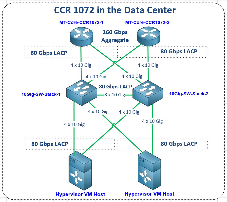
Coming next – MikroTik CCR1072-1G-8S+ Review (Part 2 ) BGP Performance testing using multiple peers with full BGP tables.
]]>