Use Case
ISPs that use MikroTik are always looking for new ways to deliver services to customers and expand their offerings. Delivering Layer 2 at scale for customers is a design challenge that comes up frequently.
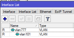
While it’s easy enough to build a VLAN nested inside of another VLAN (see below), this requires you to build all of the VLANs a customer wants to use into the PE router or handoff switch.
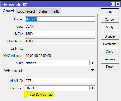
However, if you have a client that needs a layer 2 service delivered to two or more points and wants to be able to treat it just like an 802.1q trunk and add VLANs in an ad-hoc way, then using the S-Tag feature in RouterOS along with VPLS transport is a great option.
What’s the S-tag do???
Clients will often ask me “what’s the S-Tag check box for?”
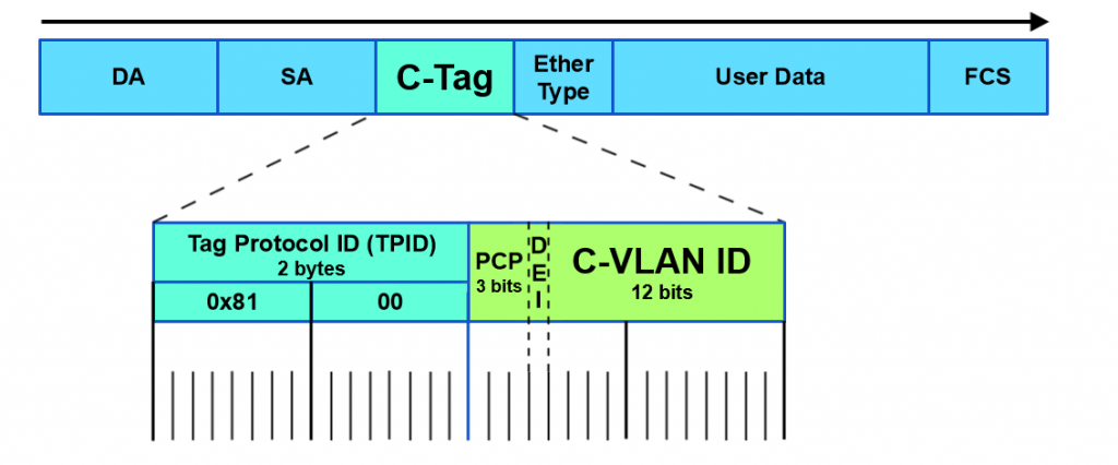
So a little background on this, there is a protocol for using outer and inner VLAN tags specified in IEEE 802.1ad that uses Service Tag (or S-Tag) to denote the outer VLAN tag used to transport Customer Tags (or C-Tags).
What makes the S-Tag/C-Tag a little bit different is that it actually changes the ethertype of the Frame.
| Protocol | Ethertype |
|---|---|
| 802.1q (Normal VLAN Tags) | 0x8100 |
| 802.1ad (S-tag) | 0x88a8 |
Here is an overview of the frame format of each and links to the Metro Ethernet Forum Wiki for more info.
S-Tag
https://wiki.mef.net/display/CESG/S-Tag

C-Tag
https://wiki.mef.net/display/CESG/C-Tag
Lab Scenario
Here is a very common example of a deployment for a Layer 2 service to an end customer that rides on top of the ISP MPLS core.
In this lab we are using Cisco switches trunked to each other using VLAN 101 and 201 over a VPLS pseudowire with an S-Tag of 777.
After configuring the P routers, PE routers and Cisco switches, let’s take a look at the Cisco switch and see if we can ping the SVI on the other switch on both trunked VLANs.
Here are the subnets used on the customer side:
Now let’s ping the .2 address for each VLAN on Switch-2
VLAN 101
VLAN 201
Notes on MTU
A note on MTU sizing, in order to hand off a 1500 byte packet with VPLS, you normally need an MPLS and L2MTU of 1530 bytes. In order to pass a second VLAN tag you’ll want to make sure your network equipment can go up to 1534 for Layer 2 and MPLS MTUs to pass 1500 byte packet with S-Tag.
Configs for the lab
In the section below, here are all the configs for this deployment
Cisco Switch-1
version 15.2
service timestamps debug datetime msec
service timestamps log datetime msec
no service password-encryption
service compress-config
!
hostname Switch-1
!
boot-start-marker
boot-end-marker
!
!
!
no aaa new-model
!
!
!
!
!
!
!
!
ip cef
no ipv6 cef
!
!
!
spanning-tree mode pvst
spanning-tree extend system-id
!
vlan internal allocation policy ascending
!
!
!
!
!
!
!
!
!
!
!
!
!
!
interface GigabitEthernet0/0
 switchport trunk encapsulation dot1q
 switchport mode trunk
 media-type rj45
 negotiation auto
!
interface GigabitEthernet0/1
 media-type rj45
 negotiation auto
!
interface GigabitEthernet0/2
 media-type rj45
 negotiation auto
!
interface GigabitEthernet0/3
 media-type rj45
 negotiation auto
!
interface GigabitEthernet1/0
 media-type rj45
 negotiation auto
!
interface GigabitEthernet1/1
 media-type rj45
 negotiation auto
!
interface GigabitEthernet1/2
 media-type rj45
 negotiation auto
!
interface GigabitEthernet1/3
 media-type rj45
 negotiation auto
!
interface Vlan101
 description customer-vlan
 ip address 192.168.101.1 255.255.255.0
!
interface Vlan201
 description customer vlan 2
 ip address 192.168.201.1 255.255.255.0
!
ip forward-protocol nd
!
no ip http server
no ip http secure-server
!
!
!
!
!
!
control-plane
!
banner exec ^C
**************************************************************************
* IOSv is strictly limited to use for evaluation, demonstration and IOS  *
* education. IOSv is provided as-is and is not supported by Cisco's      *
* Technical Advisory Center. Any use or disclosure, in whole or in part, *
* of the IOSv Software or Documentation to any third party for any       *
* purposes is expressly prohibited except as otherwise authorized by     *
* Cisco in writing.                                                      *
**************************************************************************^C
banner incoming ^C
**************************************************************************
* IOSv is strictly limited to use for evaluation, demonstration and IOS  *
* education. IOSv is provided as-is and is not supported by Cisco's      *
* Technical Advisory Center. Any use or disclosure, in whole or in part, *
* of the IOSv Software or Documentation to any third party for any       *
* purposes is expressly prohibited except as otherwise authorized by     *
* Cisco in writing.                                                      *
**************************************************************************^C
banner login ^C
**************************************************************************
* IOSv is strictly limited to use for evaluation, demonstration and IOS  *
* education. IOSv is provided as-is and is not supported by Cisco's      *
* Technical Advisory Center. Any use or disclosure, in whole or in part, *
* of the IOSv Software or Documentation to any third party for any       *
* purposes is expressly prohibited except as otherwise authorized by     *
* Cisco in writing.                                                      *
**************************************************************************^C
!
line con 0
line aux 0
line vty 0 4
!
!
end
Cisco Switch-2
version 15.2
service timestamps debug datetime msec
service timestamps log datetime msec
no service password-encryption
service compress-config
!
hostname Switch-2
!
boot-start-marker
boot-end-marker
!
!
!
no aaa new-model
!
!
!
!
!
!
!
!
ip cef
no ipv6 cef
!
!
!
spanning-tree mode pvst
spanning-tree extend system-id
!
vlan internal allocation policy ascending
!
!
!
!
!
!
!
!
!
!
!
!
!
!
interface GigabitEthernet0/0
 switchport trunk encapsulation dot1q
 switchport mode trunk
 media-type rj45
 negotiation auto
!
interface GigabitEthernet0/1
 media-type rj45
 negotiation auto
!
interface GigabitEthernet0/2
 media-type rj45
 negotiation auto
!
interface GigabitEthernet0/3
 media-type rj45
 negotiation auto
!
interface GigabitEthernet1/0
 media-type rj45
 negotiation auto
!
interface GigabitEthernet1/1
 media-type rj45
 negotiation auto
!
interface GigabitEthernet1/2
 media-type rj45
 negotiation auto
!
interface GigabitEthernet1/3
 media-type rj45
 negotiation auto
!
interface Vlan101
 description customer-vlan
 ip address 192.168.101.2 255.255.255.0
!
interface Vlan201
 description customer vlan 2
 ip address 192.168.201.2 255.255.255.0
!
ip forward-protocol nd
!
no ip http server
no ip http secure-server
!
!
!
!
!
!
control-plane
!
banner exec ^C
**************************************************************************
* IOSv is strictly limited to use for evaluation, demonstration and IOS  *
* education. IOSv is provided as-is and is not supported by Cisco's      *
* Technical Advisory Center. Any use or disclosure, in whole or in part, *
* of the IOSv Software or Documentation to any third party for any       *
* purposes is expressly prohibited except as otherwise authorized by     *
* Cisco in writing.                                                      *
**************************************************************************^C
banner incoming ^C
**************************************************************************
* IOSv is strictly limited to use for evaluation, demonstration and IOS  *
* education. IOSv is provided as-is and is not supported by Cisco's      *
* Technical Advisory Center. Any use or disclosure, in whole or in part, *
* of the IOSv Software or Documentation to any third party for any       *
* purposes is expressly prohibited except as otherwise authorized by     *
* Cisco in writing.                                                      *
**************************************************************************^C
banner login ^C
**************************************************************************
* IOSv is strictly limited to use for evaluation, demonstration and IOS  *
* education. IOSv is provided as-is and is not supported by Cisco's      *
* Technical Advisory Center. Any use or disclosure, in whole or in part, *
* of the IOSv Software or Documentation to any third party for any       *
* purposes is expressly prohibited except as otherwise authorized by     *
* Cisco in writing.                                                      *
**************************************************************************^C
!
line con 0
line aux 0
line vty 0 4
!
!
end
MikroTik PE-1
/interface bridge
add name=Lo0
add name=vpls-bridge-vlan-777
/interface vpls
add disabled=no l2mtu=1500 mac-address=02:D5:C2:72:3A:1A name=vpls777
    pw-type=tagged-ethernet remote-peer=100.127.1.2 vpls-id=8675309:777
/ip neighbor discovery
set ether2 discover=no
/interface vlan
add interface=vpls777 name=vlan777 use-service-tag=yes vlan-id=777
/interface wireless security-profiles
set [ find default=yes ] supplicant-identity=MikroTik
/routing ospf instance
add name=ospf1 router-id=100.127.1.1
/interface bridge port
add bridge=Lo0 interface=ether2
add bridge=Lo0 interface=vlan777
/ip address
add address=100.64.0.1/29 interface=ether1 network=100.64.0.0
add address=100.127.1.1 interface=Lo0 network=100.127.1.1
/ip dhcp-client
add disabled=no interface=ether1
/mpls interface
set [ find default=yes ] mpls-mtu=1534
/mpls ldp
set enabled=yes lsr-id=100.127.1.1 transport-address=100.127.1.1
/mpls ldp interface
add interface=ether1 transport-address=100.127.1.1
/routing ospf network
add area=backbone network=100.64.0.0/29
add area=backbone network=100.127.1.1/32
/system identity
set name=MikroTik-PE-1
/tool romon
set enabled=yes
MikroTik PE-2
/interface bridge
add name=Lo0
add name=vpls-bridge-vlan-777
/interface vpls
add disabled=no l2mtu=1500 mac-address=02:C1:71:EB:0E:E7 name=vpls777
    pw-type=tagged-ethernet remote-peer=100.127.1.1 vpls-id=8675309:777
/ip neighbor discovery
set ether2 discover=no
/interface vlan
add interface=vpls777 name=vlan777-s-tag use-service-tag=yes vlan-id=777
/interface wireless security-profiles
set [ find default=yes ] supplicant-identity=MikroTik
/routing ospf instance
add name=ospf1 router-id=100.127.1.2
/interface bridge port
add bridge=Lo0 interface=vlan777-s-tag
add bridge=Lo0 interface=ether2
/ip address
add address=100.64.0.18/29 interface=ether1 network=100.64.0.16
add address=100.127.1.2 interface=Lo0 network=100.127.1.2
/ip dhcp-client
add dhcp-options=hostname,clientid disabled=no interface=ether1
/mpls interface
set [ find default=yes ] mpls-mtu=1534
/mpls ldp
set enabled=yes lsr-id=100.127.1.2 transport-address=100.127.1.2
/mpls ldp interface
add interface=ether1 transport-address=100.127.1.2
/routing ospf network
add area=backbone network=100.64.0.16/29
add area=backbone network=100.127.1.2/32
/system identity
set name=MikroTik-PE-2
/tool romon
set enabled=yes
MikroTik P-CORE-1
/interface bridge
add name=Lo0
/interface vlan
add interface=ether1 name=vlan101 vlan-id=777
/interface wireless security-profiles
set [ find default=yes ] supplicant-identity=MikroTik
/routing ospf instance
set [ find default=yes ] router-id=100.127.0.1
/ip address
add address=100.64.0.2/29 interface=ether1 network=100.64.0.0
add address=100.127.0.1 interface=Lo0 network=100.127.0.1
add address=100.64.0.9/29 interface=ether2 network=100.64.0.8
/ip dhcp-client
add dhcp-options=hostname,clientid disabled=no interface=ether1
/mpls interface
set [ find default=yes ] mpls-mtu=1534
/mpls ldp
set enabled=yes lsr-id=100.127.0.1 transport-address=100.127.0.1
/mpls ldp interface
add interface=ether1 transport-address=100.127.0.1
add interface=ether2 transport-address=100.127.0.1
/routing ospf network
add area=backbone network=100.64.0.0/29
add area=backbone network=100.127.0.1/32
add area=backbone network=100.64.0.8/29
/system identity
set name=MikroTik-P-Core-1
/tool romon
set enabled=yes
MikroTik P-CORE-2
/interface bridge
add name=Lo0
/interface wireless security-profiles
set [ find default=yes ] supplicant-identity=MikroTik
/routing ospf instance
set [ find default=yes ] router-id=100.127.0.2
/ip address
add address=100.64.0.10/29 interface=ether1 network=100.64.0.8
add address=100.127.0.2 interface=Lo0 network=100.127.0.2
add address=100.64.0.17/29 interface=ether2 network=100.64.0.16
/ip dhcp-client
add dhcp-options=hostname,clientid disabled=no interface=ether1
/mpls interface
set [ find default=yes ] mpls-mtu=1534
/mpls ldp
set enabled=yes lsr-id=100.127.0.2 transport-address=100.127.0.2
/mpls ldp interface
add interface=ether1 transport-address=100.127.0.2
add interface=ether2 transport-address=100.127.0.2
/routing ospf network
add area=backbone network=100.64.0.8/29
add area=backbone network=100.127.0.2/32
add area=backbone network=100.64.0.16/29
/system identity
set name=MikroTik-P-Core-2
/tool romon


