PDF link is here
A reference guide for new & existing ISPs that need to understand network functions and separation.
“How do I add redundancy?”
“How do I scale?”
“How do I reduce downtime and operational costs?”
These are questions that I get asked practically every day as a consulting network architect that designs and builds ISPs.
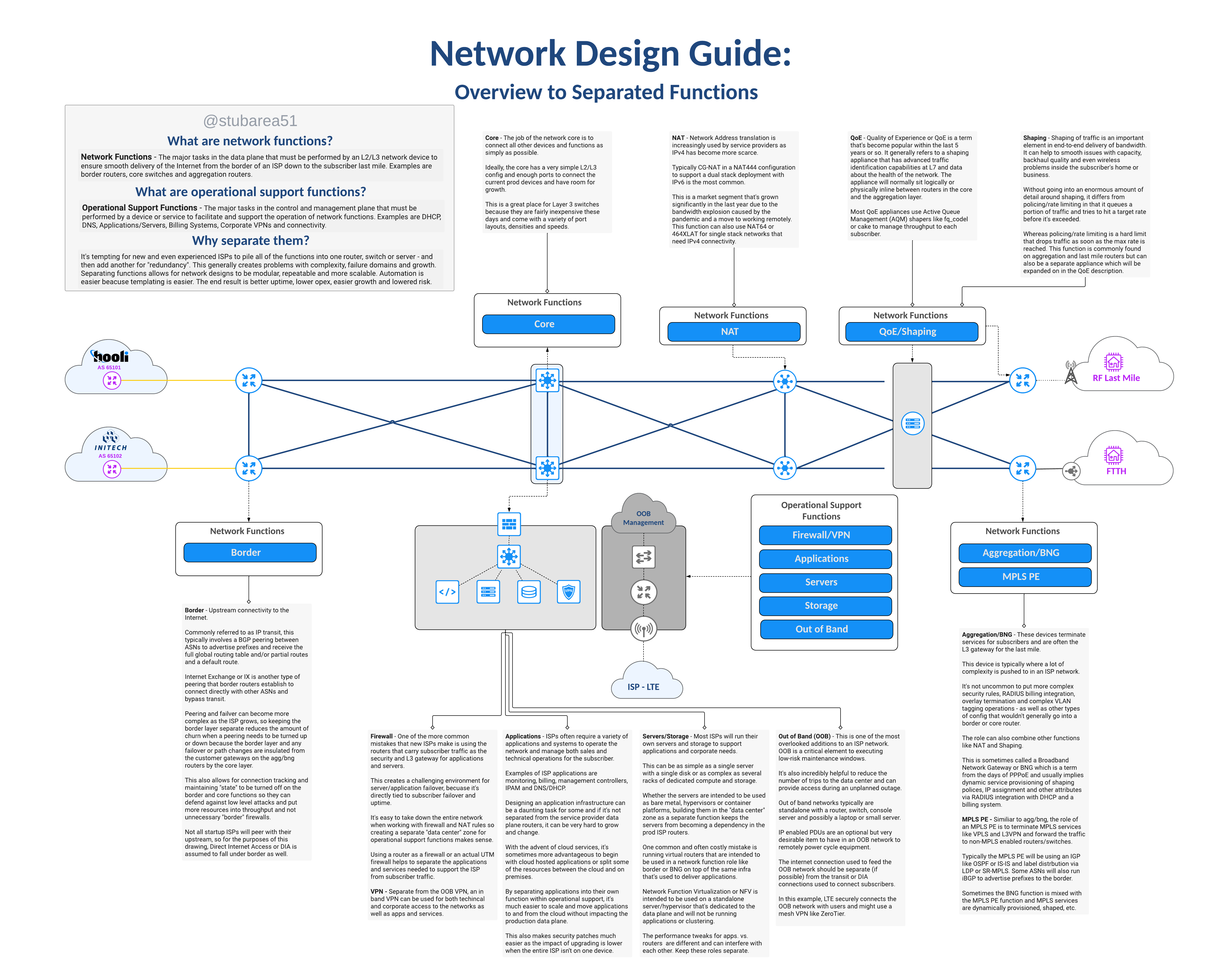
In most cases the answer is the same whether the ISP uses fixed wireless broadband, copper or fiber to deliver the last mile – separation of network functions.
This illustrated guide is intended to define the topic and create visual context for each function using a network drawing. It’s the first in a new series on this subject.
A new series of content
This topic is deep and there is a lot to unpack so this will be the first segment in a series of blog posts and videos covering function separation.
Large ISPs typically already embrace the philosophy of separating network functions, so the focus of this series will be to help new or growing regional ISPs understand the design intent and the challenges/costs of running networks that don’t separate network functions.