MikroTik RouterOS new feature – Loop Protect


‘Loop Protect’ – New feature in 6.37rc24

Long-time MikroTik users have been after better loop prevention mechanisms for quite a while now. Rapid STP within bridges was the only feature available up until Fall of 2016 and now MikroTik has released Rapid Spanning Tree in hardware for switched ports as well as a new Loop Protect feature that seems to serve the same function as Cisco’s Loop Guard but not utilize spanning tree to detect the loop. MikroTik’s version compares the source MAC of the loop protect frame with the MAC of the interface it is received on and if they match, it will disable the port until the timer expires and check again for the existence of a loop.

This feature was introduced in 6.37rc24 on August 31st, 2016.

LoopProtect-changelog

http://wiki.mikrotik.com/wiki/Manual:Loop_Protect

Use cases for ‘Loop Protect’

Loop protect seems to be designed more as an edge port protocol since it physically disables the port upon detection of a loop, whereas STP will leave the port physically active but logically block traffic on that path.  Some potential use cases for enabling this feature could include:

  • Edge port on a MikroTik device facing the end subscriber equipment – this would cut down on loops (and outages) that feed back into the ISP because of subscribers plugging in “dumb” switches, hubs or bridged routers.
  • Edge port for an Enterprise or SMB user device to prevent loops causing a larger outage from unauthorized switches/hubs that have been plugged in on the edge port.
  • Data Center edge port for servers, routers or other devices that shouldn’t create a loop but still have the capacity to do so. An example would be a mis-configured vSwitch in a hypervisor.
  • Downstream switch connected to a router or switch that doesn’t have a physical topology that will allow a loop in normal operation, however, a cable plugged into two ports on the same switch or a down stream switch could still send a broadcast storm towards the port.

‘Loop Protect’ in the StubArea51 test lab

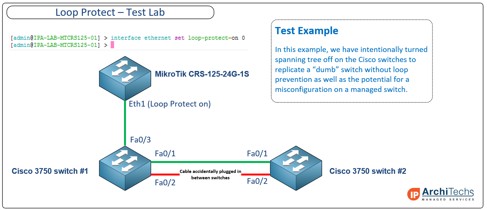
Below is an example lab we built to test the Loop protect feature. The idea was to intentionally create a loop between two Cisco 3750 switches that would propagate looped frames and broadcasts towards the ethernet port on a MikroTik CRS125 with Loop Protect enabled.

Click on the image for a larger version

LoopProtectLab

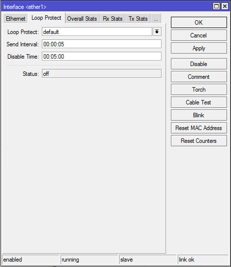
Enabling the ‘Loop Protect’ feature in WinBox

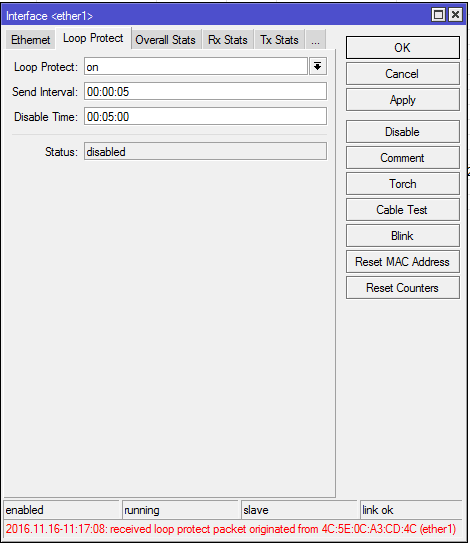
By default, the feature is disabled. To enable it, you select the interface to enable it on –> navigate to the ‘Loop Protect’ tab –> select the first drop down menu and set it to on (some versions of 6.37 have a bug that show more than the three available settings of default,on and off). You can also adjust the ‘Send Interval’ which controls how frequently Loop Protect frames are sent out of the interface. There is a ‘Disable Time’ value that can be set which starts counting down as soon as a loop is detected and will bring the interface back online after the timer is expired and check again for the existence of a loop. This interface will cycle through disabling the interface and the disable timer so long as a loop is present.

LoopProtect-default-off

Detecting a loop with ‘Loop Protect’ enabled 

In the hardware lab above, we connected a second cable between two Cisco 3750 switches with spanning tree turned off and ‘Loop Protect’ detected the loop almost immediately as indicated by the message in red at the bottom of the picture below. The status has now been changed to disabled until the loop clears and the disable timer expires.

LoopProtect-Enabled with a loop detected

‘Loop Protect’ in the log

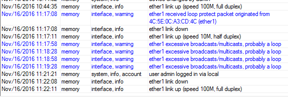
Like all good features, ‘Loop Protect” will add status messages to the log which show the following as the loop is detected and then cleared. If you send your log messages to an external syslog server, then you can create alerts to let you know when a port has gone down due to a loop.

  • 11:17:08 – Loop is detected
  • 11:17:08 – ether1 goes into disabled state
  • 11:22:11 – The loop is cleared by the disable timer expiring (after unplugging the rogue cable between switches)
LoopProtect-log

WISP Design: Using OSPF to build a transit fabric over unequal links


Defining the problem – unused capacity

One of the single greatest challenges if you have ever owned, operated or designed a WISP (Wireless Internet Service Provider) is using all of the available bandwidth across multiple PtP links in the network. It is very common for two towers to have multiple RF PtP (Point-to-Point) links between them and run at different speeds. It is not unusual to have a primary link that runs at near-gigabit speeds and a backup link that may range anywhere from 50 Mbps to a few hundred Mbps.

This provides a pretty clean HA routing architecture, but it leaves capacity in the network unused until there is a failure. One of the headaches WISP designers always face is how to manage and engineer traffic for sub-rate ethernet links – essentially links that can’t deliver as much throughput as the physical link to the router or switch. In the fiber world, this is pretty straightforward as two links between any two points can be the exact same speed and either be channeled together with LACP or rely on ECMP with OSPF or BGP.

However, in the WISP world, this becomes problematic, as the links are unequal and neither channeling or ECMP has been an effective solution as it leaves bandwidth unused on the higher speed link.

Previous attempts to solve the problem

SolutionDescription/Caveats
Scripting / PCQScripting and Per-Connection-Queuing is a technique that many have used with some success but it adds a moderate amount of complexity and struggles when the disparity between the speeds of links is more than 4 to 1.
Scripting / Routing MarksScripting and using routing marks allows you to change the next hop of traffic when a link reaches a certain capacity, but it also adds moderate complexity and adding a routing mark for anything beyond one extra link becomes tedious.
MPLS Traffic EngineeringMPLS Traffic Engineering has the distinct advantage of selecting exactly which hops traffic to a certain destination will take but it requires an experienced hand to get it working and some care and feeding to monitor and adjust the properties of the TE tunnels. MPLS TE is probably the most complex solution out of the 4 listed options.
External Load BalancerThis is the most effective solution as it can dynamically balance traffic across links of any speed but it requires setup, maintenance and a bunch of extra hardware (and money), especially if you want to make it HA.

Why not EIGRP?

If you’re a seasoned network engineer, you may be thinking in the back of your head there is a routing protocol that solves this exact problem and you would be right – EIGRP! The main problem with EIGRP is that it is still exclusively a Cisco protocol. Like most networks today, WISPs are typically very multi-vendor (and rarely Cisco outside of the core) and although EIGRP was released as an open standard a few years ago, there hasn’t been any movement by software developers  to incorporate it in network operating systems.

Current solution – OSPF COST

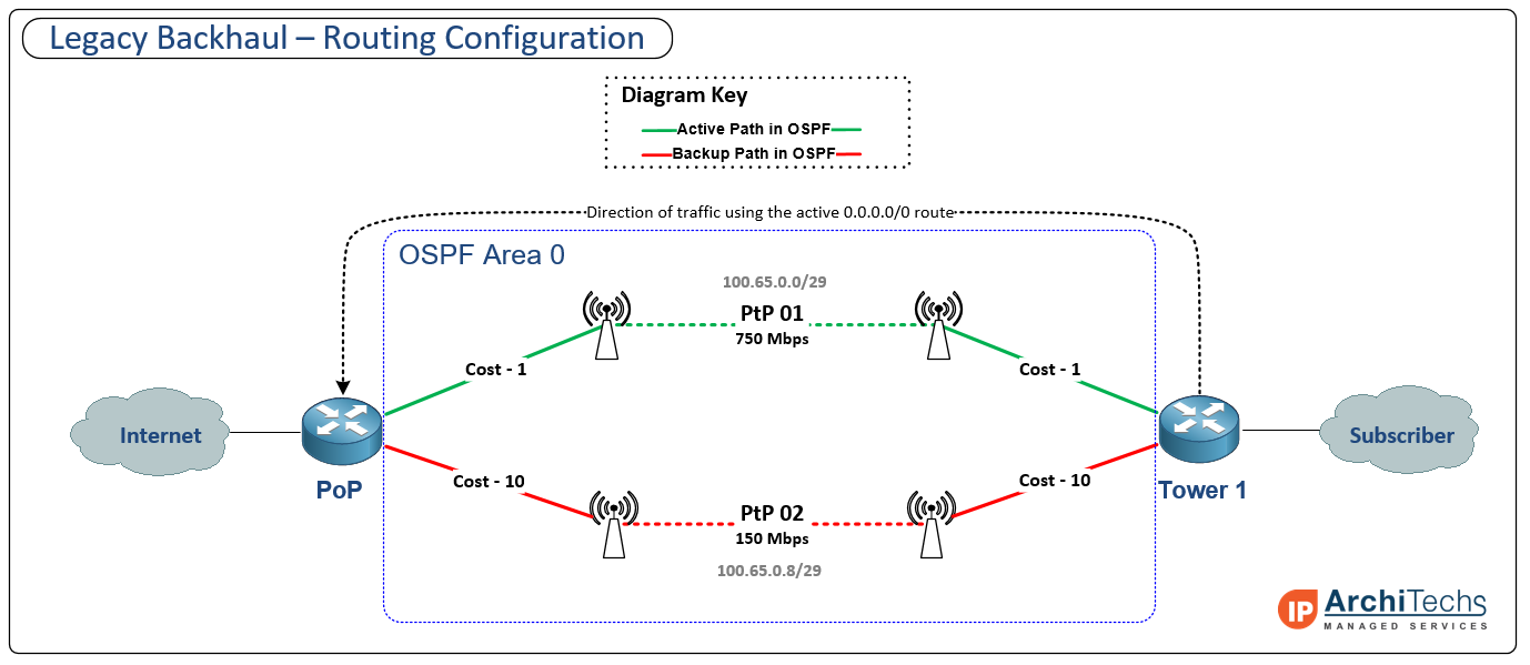
Here is an example of a typical WISP active/backup path design using OSPF cost to control path selection. This isn’t the only way to leverage active/backup paths, but is one of the most common we see in production WISPs today.

click on the image for a larger version

TransitFabric-Legacy-final

Designing a transit fabric using OSPF, ECMP and VLANs

It is probably helpful to first define what a fabric is before getting into how we are going to build it. Russ White recently published an excellent guide on what constitutes a “fabric” that can be found here. One of the key points he makes is that large numbers of ECMP paths generally lend to calling the design a fabric rather than a network.

We set out to solve this problem because we recently had a client that was using a load balancer to achieve unequal cost load balancing and needed more capacity than the box could provide. As is the case in many WISPs, we were working with MikroTik routers throughout the network and had to find a way to increase capacity, preserve the load balancing ratio and not introduce an enormous amount of complexity. We experimented with a number of different solutions using scripting, queuing and MPLS TE, but couldn’t find anything that worked as well as a load balancer and would failover cleanly and quickly without more rounds of scripting and patchwork solutions.

The Eureka moment!

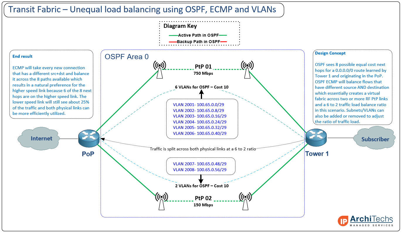
After multiple trips to the Keurig and Whiteboard, we finally hit upon an idea that sounded a bit crazy at first but would actually work to turn OSPF into a protocol that could handle unequal load balancing. Since OSPF already has a mechanism for load balancing over equal cost next hops, we began to realize that if we could get OSPF to see more next hops available than we had physical links available, we could tailor the number of next hops available across each link to achieve unequal load balancing with ECMP.  The key is to use trusty old VLANs to allow multiple logical paths between the two physical paths and then build more VLANs over the link with higher capacity. As the design took shape, we realized that it represented a fabric more so than a collection of independent links and thus the transit fabric was born.

Defining the traffic ratio

Since this was getting into uncharted territory, we realized that we needed a baseline for a ratio of how many VLANs to build on each path. We decided to divide the total available bandwidth (900 Mbps in this example) by the lowest speed link (150 Mbps) which resulted in a 6 to 1 traffic ratio. You might realize at this point that we ended up using a 6 to 2 ratio in our lab test instead of 6 to 1. The main reason for this is that we wanted to start out with a number of total next hops that fell on a common ECMP boundary (2,4,8,16, etc) so we increased the number of VLANs from 7 to 8. One of the really neat aspects of this design is that you can create and remove VLANs to adjust the load balancing ratio of traffic so that you can tune the performance to a specific deployment. The end result is that our initial lab build worked very well with 8 VLANs and did exactly what we wanted when we lit up multiple downloads – traffic was balanced across all links according to the link capacity.

Topology of the transit fabric

click on the image for a larger version

TransitFabric-New-final

Out of the whiteboard and into real gear

We decided to build a lab to test this theory and put real hardware behind it, so we grabbed a handful of MikroTIk CCRs, Cisco 3750 Switches, a few test laptops and an Internet connection. We put it all together in roughly the same fashion as the diagram above – although we had different VLAN numbering and physical config since we were testing a production network. Once we got the network built and rate limited our links to mimic sub-rate Ethernet, a few laptops were hung off of the subscriber side to generate traffic and test the scattering of packets.

Transit fabric in action – forwarding down all links with unequal traffic balancing

Default route status with multiple paths available via ECMP (note: in this network, we are using BGP end-to-end and OSPF only for next hop/loopback reachability)

Default route-transit fabric

  • First PtP – 6 Mbps across 2 VLANs
  • Second PtP – 23 Mbps across 6 VLANs

LabTest-Transit Fabric