About the Juniper to MikroTik series
In the world of network engineering, learning a new syntax for a NOS can be daunting if you need a specific config quickly. Juniper is a popular option for service providers/data centers and is widely deployed across the world.
This is a continuation of the Rosetta stone for network operating systems series. In this article we will be covering multi-protocol label switching (MPLS) using label distribution protocol (LDP). We are sticking with LDP as MikroTik does not have wide support for RSVP-TE.
You can find the first two articles of the series here:
Juniper to MikroTik – BGP commands
Juniper to MikroTik – OSPF commands
While many commands have almost the exact same information, others are as close as possible. Since there isn’t always an exact match, sometimes you may have to run two or three commands to get the information needed.
Using EVE-NG for testing
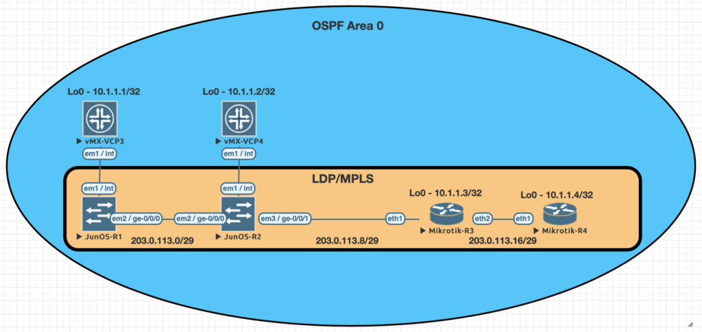
We conducted utilized EVE-NG for all of the testing with the topology seen below.
| Juniper Command | MikroTik Command |
|---|---|
| show ldp neighbor | mpls ldp neighbor print |
| show ldp interface | mpls ldp interface print |
| show route forwarding-table family mpls | mpls forwarding-table print |
| show ldp database | mpls remote-bindings print |
| show ldp database | mpls local-bindings print |
| show mpls label usage | mpls print |
| set interfaces ge-0/0/0 unit 0 family mpls set protocols ldp interface ge-0/0/0.0 | /mpls ldp interface add interface=ether1 |
| set routing-options router-id 10.1.1.1 | /mpls ldp set enabled=yes lsr-id=10.1.1.3 |
Examples of the commands above
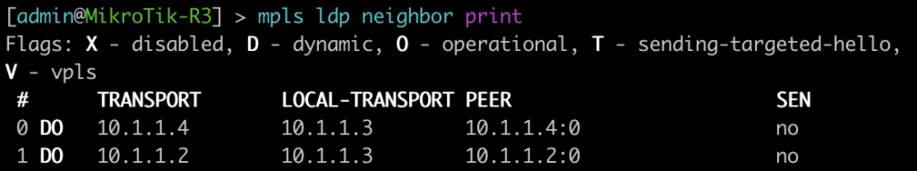
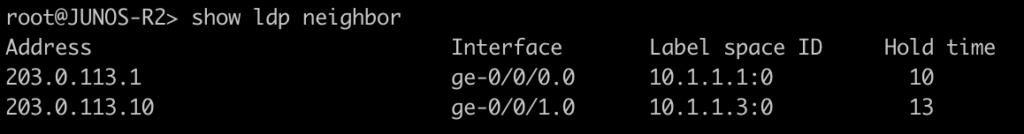
This first command will show you some basic information about your MPLS LDP neighbors. On juniper you can add the keyword detail to the end for additional information on the neighbors.
[admin@MikroTik-R3] > mpls ldp neighbor print
root@JUNOS-R2> show ldp neighbor
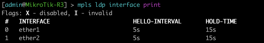
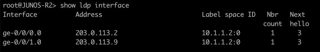
This command will list all of the interfaces that are currently enabled for LDP.
[admin@MikroTik-R3] > mpls ldp interface print
root@JUNOS-R2> show ldp interface
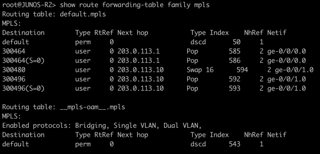
Use this command to display the MPLS forwarding table which shows what labels are assigned, the interface used and the next-hop. It will also tell you the action taken such as pop, swap, or push.
[admin@MikroTik-R3] > mpls forwarding-table print
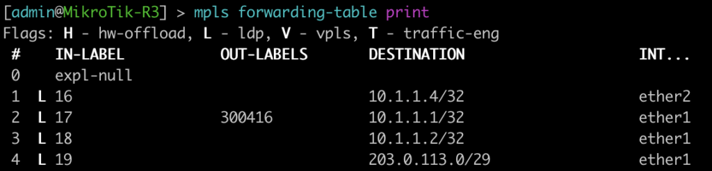
root@JUNOS-R2> show route forwarding-table family mpls
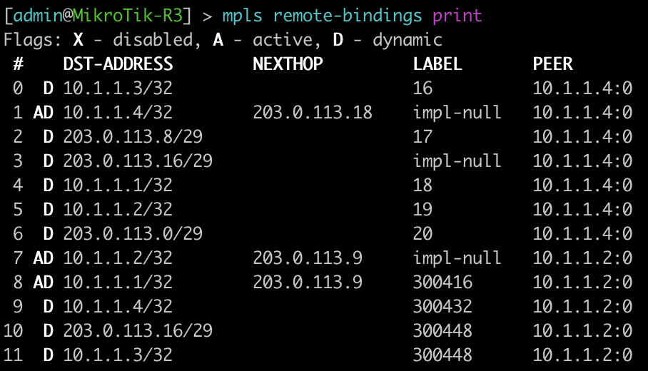
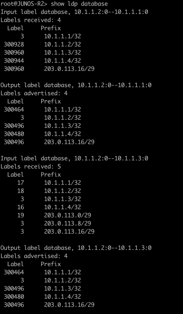
The next two commands will be combined since juniper only has one command to be equivalent to mikrotiks output. This is will show the advertised and received labels for all of the prefixes known to LDP as well as the label associated with it and where it was learned from. On JunOS you will notice label 3. This is juiper’s method to signal implicit null and request label popping by the downstream router.
[admin@MikroTik-R3] > mpls remote-bindings print
[admin@MikroTik-R3] > mpls local-bindings print
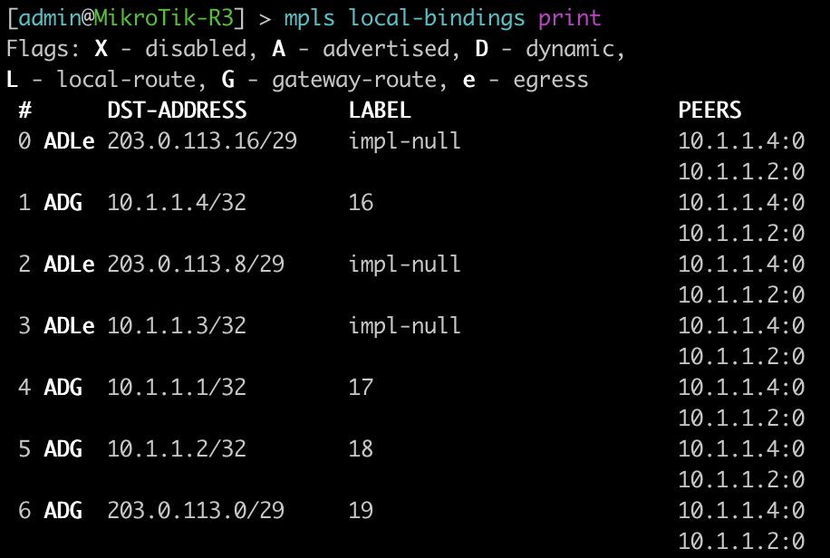
root@JUNOS-R2> show ldp database
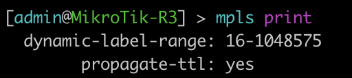
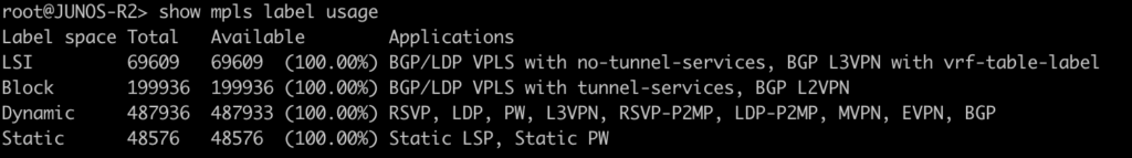
This last command will show the label ranges and what they are used for.
[admin@MikroTik-R3] > mpls print
root@JUNOS-R2> show mpls label usage
Configurations
root@JUNOS-R1# show | display set
set version 18.2R1.9
set system root-authentication encrypted-password "$6$iCt/DOMc$lQFrIQdrjot1m0lIY5A2eUaOmat87oAqbNZWd/3KPij2QWTlBQEyYlVbb1/emd2N9VKN6NL0olk.kJK7mLcgM0"
set system host-name JUNOS-R1
set system syslog user * any emergency
set system syslog file messages any notice
set system syslog file messages authorization info
set system syslog file interactive-commands interactive-commands any
set system processes dhcp-service traceoptions file dhcp_logfile
set system processes dhcp-service traceoptions file size 10m
set system processes dhcp-service traceoptions level all
set system processes dhcp-service traceoptions flag packet
set interfaces ge-0/0/0 unit 0 family inet address 203.0.113.1/29
set interfaces ge-0/0/0 unit 0 family mpls
set interfaces fxp0 unit 0 family inet dhcp vendor-id Juniper-vmx-VM6015C6C2F2
set interfaces lo0 unit 0 family inet address 10.1.1.1/32
set routing-options router-id 10.1.1.1
set protocols ospf area 0.0.0.0 interface ge-0/0/0.0
set protocols ospf area 0.0.0.0 interface lo0.0 passive
set protocols ldp interface ge-0/0/0.0
root@JUNOS-R2# show | display set
set version 18.2R1.9
set system root-authentication encrypted-password "$6$x.MmgodX$XG1D3lCYPC8VpIhE8NXxdRJaoZS8sYB2PB0v50POrrx6Mi.nhnTB/41NGFk1zL8RDQBdR/lCPG2NazFDYgzNf/"
set system host-name JUNOS-R2
set system syslog user * any emergency
set system syslog file messages any notice
set system syslog file messages authorization info
set system syslog file interactive-commands interactive-commands any
set system processes dhcp-service traceoptions file dhcp_logfile
set system processes dhcp-service traceoptions file size 10m
set system processes dhcp-service traceoptions level all
set system processes dhcp-service traceoptions flag packet
set interfaces ge-0/0/0 unit 0 family inet address 203.0.113.2/29
set interfaces ge-0/0/0 unit 0 family mpls
set interfaces ge-0/0/1 unit 0 family inet address 203.0.113.9/29
set interfaces ge-0/0/1 unit 0 family mpls
set interfaces fxp0 unit 0 family inet dhcp vendor-id Juniper-vmx-VM6015C6C3B3
set interfaces lo0 unit 0 family inet address 10.1.1.2/32
set routing-options router-id 10.1.1.2
set protocols ospf area 0.0.0.0 interface ge-0/0/0.0
set protocols ospf area 0.0.0.0 interface ge-0/0/1.0
set protocols ospf area 0.0.0.0 interface lo0.0 passive
set protocols ldp interface ge-0/0/0.0
set protocols ldp interface ge-0/0/1.0[admin@MikroTik-R3] > export
# jan/31/2021 20:52:19 by RouterOS 6.46.8
# software id =
#
#
#
/interface bridge
add name=Loopback0
/interface wireless security-profiles
set [ find default=yes ] supplicant-identity=MikroTik
/ip address
add address=203.0.113.10/29 interface=ether1 network=203.0.113.8
add address=10.1.1.3 interface=Loopback0 network=10.1.1.3
add address=203.0.113.17/29 interface=ether2 network=203.0.113.16
/ip dhcp-client
add disabled=no interface=ether2
add disabled=no interface=ether1
/mpls ldp
set enabled=yes lsr-id=10.1.1.3
/mpls ldp interface
add interface=ether1
add interface=ether2
/routing ospf network
add area=backbone network=203.0.113.8/29
add area=backbone network=10.1.1.3/32
add area=backbone network=203.0.113.16/29
/system identity
set name=MikroTik-R3[admin@MikroTik-R4] > export
# jan/31/2021 21:06:10 by RouterOS 6.46.8
# software id =
#
#
#
/interface bridge
add name=Loopback0
/interface wireless security-profiles
set [ find default=yes ] supplicant-identity=MikroTik
/ip address
add address=203.0.113.18/29 interface=ether1 network=203.0.113.16
add address=10.1.1.4 interface=Loopback0 network=10.1.1.4
/ip dhcp-client
add disabled=no interface=ether2
add disabled=no interface=ether1
/mpls ldp
set enabled=yes lsr-id=10.1.1.4
/mpls ldp interface
add interface=ether1
/routing ospf network
add area=backbone network=203.0.113.16/29
add area=backbone network=10.1.1.4/32
/system identity
set name=MikroTik-R4Thanks for joining us for this series and check back soon for more posts.