About the Cisco to MikroTik series
One of the hardest things to do quickly in network engineering, is learn a new syntax for a NOS. Especially if you have a tight deadline and need to stand up equipment you’ve never worked with before. The command structure for RouterOS can be cumbersome if you are used to the Cisco CLI.
If you’ve been in networking for a while, you probably started with learning the Cisco CLI. Therefore, it is helpful to compare the commands if you want to implement a network with a MikroTik and Cisco routers.
This is the third post in a series that creates a Rosetta stone between IOS and RouterOS. We plan to tackle other command comparisons like VLANs, QoS and basic operations to make it easier for network engineers trained in Cisco IOS to successfully implement Mikrotik / RouterOS devices.
Click here for the first article in this series – “Cisco to MikroTik BGP command translation”
Click here for the second article in this series – “Cisco to MikroTik OSPF command translation”
While many commands have almost the exact same information, others are as close as possible. Since there isn’t always an exact match, sometimes you may have to run two or three commands to get the information needed.
Using EVE-NG for testing
In the last article, we began using EVE-NG instead of GNS3 to emulate both Cisco IOS and RouterOS so we could compare the different commands and ensure the translation was as close as possible. Don’t get me wrong, I like GNS3, but the web interface of EVE-NG makes it really easy to keep all the horsepower for complex labs at a central location and then VPN in to work on labs as needed.
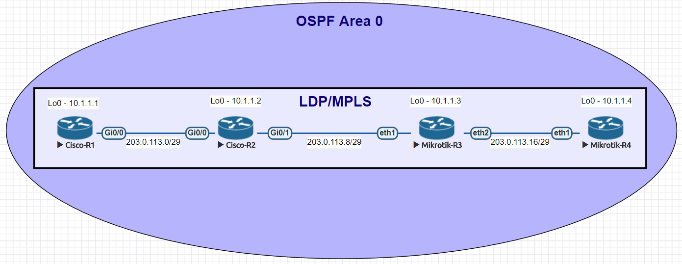
Network for Basic mpls commands
| Cisco command | MikroTik Command |
|---|---|
| show mpls ldp neighbor | mpls ldp neighbor print |
| show mpls interfaces | mpls ldp interface print |
| show mpls forwarding-table | mpls forwarding-table print |
| show mpls binding | mpls remote-bindings print |
| sh mpls ip binding local | mpls local-bindings print |
| sh mpls label range | mpls print |
| sh mpls ldp parameters | mpls ldp print |
| interface GigabitEthernet0/1 mpls ip | /mpls ldp interface add interface=ether1 |
| mpls ldp router-id Loopback0 | /mpls ldp set enabled=yes lsr-id=10.1.1.3 |
Examples of the MikroTik RouterOS commands from the table above
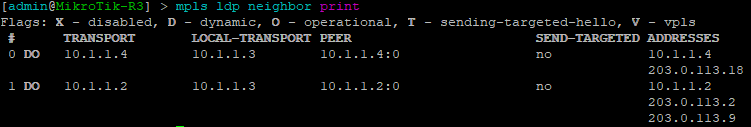
[admin@MikroTik] > mpls ldp neighbor print
This command will show LDP neighbors and detail on whether they are Dynamic, Targeted, Operational or using VPLS
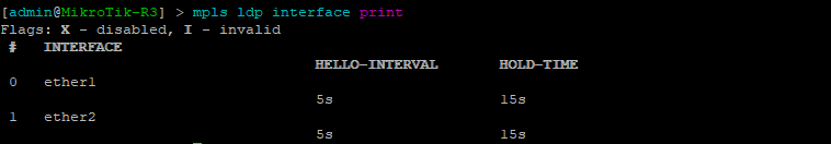
[admin@MikroTik] > mpls ldp interface print
This command will list the interfaces that LDP is enabled on
[admin@MikroTik] > mpls forwarding-table print
Use this command to display the MPLS forwarding table which shows what labels are assigned, the interface used and the next hop.

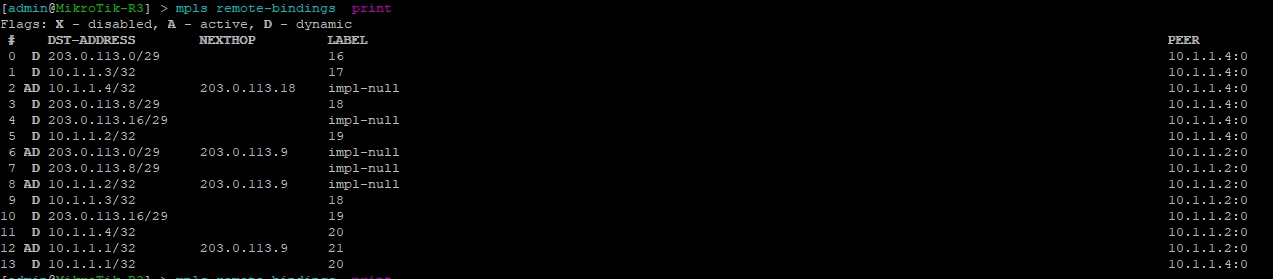
[admin@MikroTik] > mpls remote-bindings print
This is a quick way to show remote bindings which displays the labels desired and used by the next hop routers for each prefix.
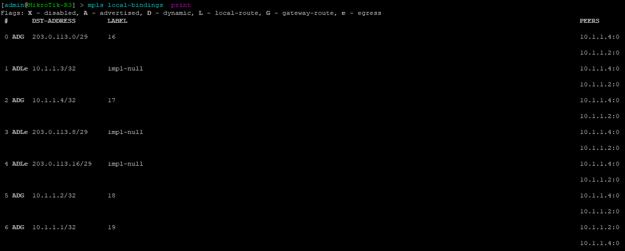
[admin@MikroTik] > mpls local-bindings print
This is a quick way to show local bindings which displays the labels desired and used by the local router – in this case R3.
[admin@MikroTik] > mpls print
This is a quick way to show basic mpls settings for RouterOS which includes the label range and whether or not to propagate TTL which affects what a traceroute looks like over an MPLS network.

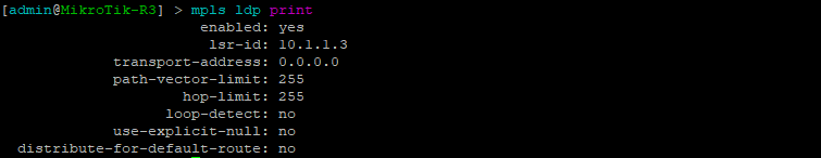
[admin@MikroTik] > mpls ldp print
This is a quick way to show mpls ldp settings for Router-OS including whether or not LDP is enabled.
Configurations
R1
Cisco-R1#sh run
Building configuration...

Current configuration : 3062 bytes
!
version 15.5
service timestamps debug datetime msec
service timestamps log datetime msec
no service password-encryption
!
hostname Cisco-R1
!
boot-start-marker
boot-end-marker
!
!
!
no aaa new-model
ethernet lmi ce
!
!
!
mmi polling-interval 60
no mmi auto-configure
no mmi pvc
mmi snmp-timeout 180
!
!
!
!
!
!
!
!
!
!
!
ip cef
no ipv6 cef
!
multilink bundle-name authenticated
!
!
!
!
!
redundancy
!
!
!
!
!
!
!
!
!
!
!
!
!
!
!
interface Loopback0
 ip address 10.1.1.1 255.255.255.255
!
interface GigabitEthernet0/0
 ip address 203.0.113.1 255.255.255.248
 duplex auto
 speed auto
 media-type rj45
 mpls ip
!
interface GigabitEthernet0/1
 no ip address
 shutdown
 duplex auto
 speed auto
 media-type rj45
!
interface GigabitEthernet0/2
 no ip address
 shutdown
 duplex auto
 speed auto
 media-type rj45
!
interface GigabitEthernet0/3
 no ip address
 shutdown
 duplex auto
 speed auto
 media-type rj45
!
router ospf 1
 network 10.1.1.1 0.0.0.0 area 0
 network 203.0.113.0 0.0.0.7 area 0
!
ip forward-protocol nd
!
!
no ip http server
no ip http secure-server
!
!
!
mpls ldp router-id Loopback0
!
control-plane
!
banner exec ^C
**************************************************************************
* IOSv is strictly limited to use for evaluation, demonstration and IOS  *
* education. IOSv is provided as-is and is not supported by Cisco's      *
* Technical Advisory Center. Any use or disclosure, in whole or in part, *
* of the IOSv Software or Documentation to any third party for any       *
* purposes is expressly prohibited except as otherwise authorized by     *
* Cisco in writing.                                                      *
**************************************************************************^C
banner incoming ^C
**************************************************************************
* IOSv is strictly limited to use for evaluation, demonstration and IOS  *
* education. IOSv is provided as-is and is not supported by Cisco's      *
* Technical Advisory Center. Any use or disclosure, in whole or in part, *
* of the IOSv Software or Documentation to any third party for any       *
* purposes is expressly prohibited except as otherwise authorized by     *
* Cisco in writing.                                                      *
**************************************************************************^C
banner login ^C
**************************************************************************
* IOSv is strictly limited to use for evaluation, demonstration and IOS  *
* education. IOSv is provided as-is and is not supported by Cisco's      *
* Technical Advisory Center. Any use or disclosure, in whole or in part, *
* of the IOSv Software or Documentation to any third party for any       *
* purposes is expressly prohibited except as otherwise authorized by     *
* Cisco in writing.                                                      *
**************************************************************************^C
!
line con 0
line aux 0
line vty 0 4
 login
 transport input none
!
no scheduler allocate
!
end
R2
Cisco-R2#sh run
Building configuration...

Current configuration : 3122 bytes
!
version 15.5
service timestamps debug datetime msec
service timestamps log datetime msec
no service password-encryption
!
hostname Cisco-R2
!
boot-start-marker
boot-end-marker
!
!
!
no aaa new-model
ethernet lmi ce
!
!
!
mmi polling-interval 60
no mmi auto-configure
no mmi pvc
mmi snmp-timeout 180
!
!
!
!
!
!
!
!
!
!
!
ip cef
no ipv6 cef
!
multilink bundle-name authenticated
!
!
!
!
!
redundancy
!
!
!
!
!
!
!
!
!
!
!
!
!
!
!
interface Loopback0
 ip address 10.1.1.2 255.255.255.255
!
interface GigabitEthernet0/0
 ip address 203.0.113.2 255.255.255.248
 duplex auto
 speed auto
 media-type rj45
 mpls ip
!
interface GigabitEthernet0/1
 ip address 203.0.113.9 255.255.255.248
 duplex auto
 speed auto
 media-type rj45
 mpls ip
!
interface GigabitEthernet0/2
 no ip address
 shutdown
 duplex auto
 speed auto
 media-type rj45
!
interface GigabitEthernet0/3
 no ip address
 shutdown
 duplex auto
 speed auto
 media-type rj45
!
router ospf 1
 network 10.1.1.2 0.0.0.0 area 0
 network 203.0.113.0 0.0.0.7 area 0
 network 203.0.113.8 0.0.0.7 area 0
!
ip forward-protocol nd
!
!
no ip http server
no ip http secure-server
!
!
!
mpls ldp router-id Loopback0
!
control-plane
!
banner exec ^C
**************************************************************************
* IOSv is strictly limited to use for evaluation, demonstration and IOS  *
* education. IOSv is provided as-is and is not supported by Cisco's      *
* Technical Advisory Center. Any use or disclosure, in whole or in part, *
* of the IOSv Software or Documentation to any third party for any       *
* purposes is expressly prohibited except as otherwise authorized by     *
* Cisco in writing.                                                      *
**************************************************************************^C
banner incoming ^C
**************************************************************************
* IOSv is strictly limited to use for evaluation, demonstration and IOS  *
* education. IOSv is provided as-is and is not supported by Cisco's      *
* Technical Advisory Center. Any use or disclosure, in whole or in part, *
* of the IOSv Software or Documentation to any third party for any       *
* purposes is expressly prohibited except as otherwise authorized by     *
* Cisco in writing.                                                      *
**************************************************************************^C
banner login ^C
**************************************************************************
* IOSv is strictly limited to use for evaluation, demonstration and IOS  *
* education. IOSv is provided as-is and is not supported by Cisco's      *
* Technical Advisory Center. Any use or disclosure, in whole or in part, *
* of the IOSv Software or Documentation to any third party for any       *
* purposes is expressly prohibited except as otherwise authorized by     *
* Cisco in writing.                                                      *
**************************************************************************^C
!
line con 0
line aux 0
line vty 0 4
 login
 transport input none
!
no scheduler allocate
!
end
R3
[admin@MikroTik-R3] > export
# may/03/2018 16:34:51 by RouterOS 6.38.7
# software id =
#
/interface bridge
add name=Loopback0
/interface wireless security-profiles
set [ find default=yes ] supplicant-identity=MikroTik
/ip address
add address=203.0.113.10/29 interface=ether1 network=203.0.113.8
add address=10.1.1.3 interface=Loopback0 network=10.1.1.3
add address=203.0.113.17/29 interface=ether2 network=203.0.113.16
/ip dhcp-client
add disabled=no interface=ether1
/mpls ldp
set enabled=yes lsr-id=10.1.1.3
/mpls ldp interface
add interface=ether1
add interface=ether2
/routing ospf network
add area=backbone network=203.0.113.8/29
add area=backbone network=10.1.1.3/32
add area=backbone network=203.0.113.16/29
/system identity
set name=MikroTik-R3
R4
[admin@MikroTik-R4] > export
# may/03/2018 16:35:28 by RouterOS 6.38.7
# software id =
#
/interface bridge
add name=Loopback0
/interface wireless security-profiles
set [ find default=yes ] supplicant-identity=MikroTik
/ip address
add address=203.0.113.18/29 interface=ether1 network=203.0.113.16
add address=10.1.1.4 interface=Loopback0 network=10.1.1.4
/ip dhcp-client
add disabled=no interface=ether1
/mpls ldp
set enabled=yes lsr-id=10.1.1.4
/mpls ldp interface
add interface=ether1
/routing ospf network
add area=backbone network=203.0.113.16/29
add area=backbone network=10.1.1.4/32
/system identity
set name=MikroTik-R4