We have a Facebook group!
If you’re into whitebox, disaggregated or commodity networking, come join the StubArea51.net Facebook group!
All network geeks are welcome 😉
| ||||||||
If you’re into whitebox, disaggregated or commodity networking, come join the StubArea51.net Facebook group!
All network geeks are welcome 😉
| ||||||||
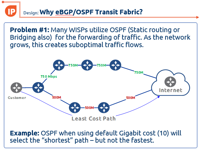
One of the latest designs I have been working on is using eBGP and an OSPF transit fabric to provide traffic engineering and load balancing. If you missed this presentation at the 2017 MikroTik User Meeting in Denver, CO, here are the slides:
WISP-Design-Using-eBGP-and-OSPF-TF-traffic-engineering-MUM-2017_KevinMyers-4-by-3
