When troubleshooting OSPF in MikroTik, it’s often helpful to look at the LSAs to determine the root cause of an issue.
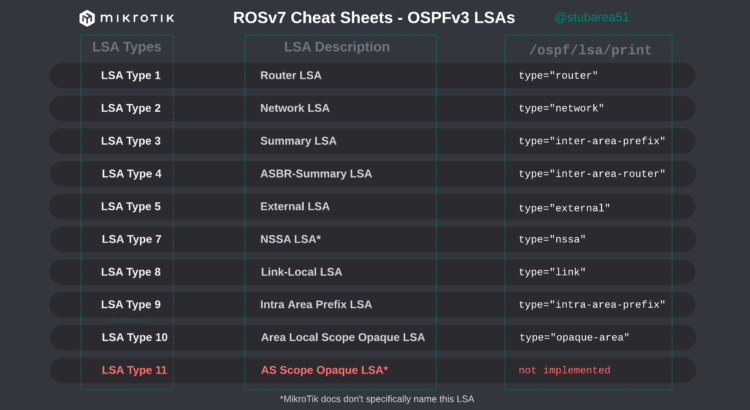
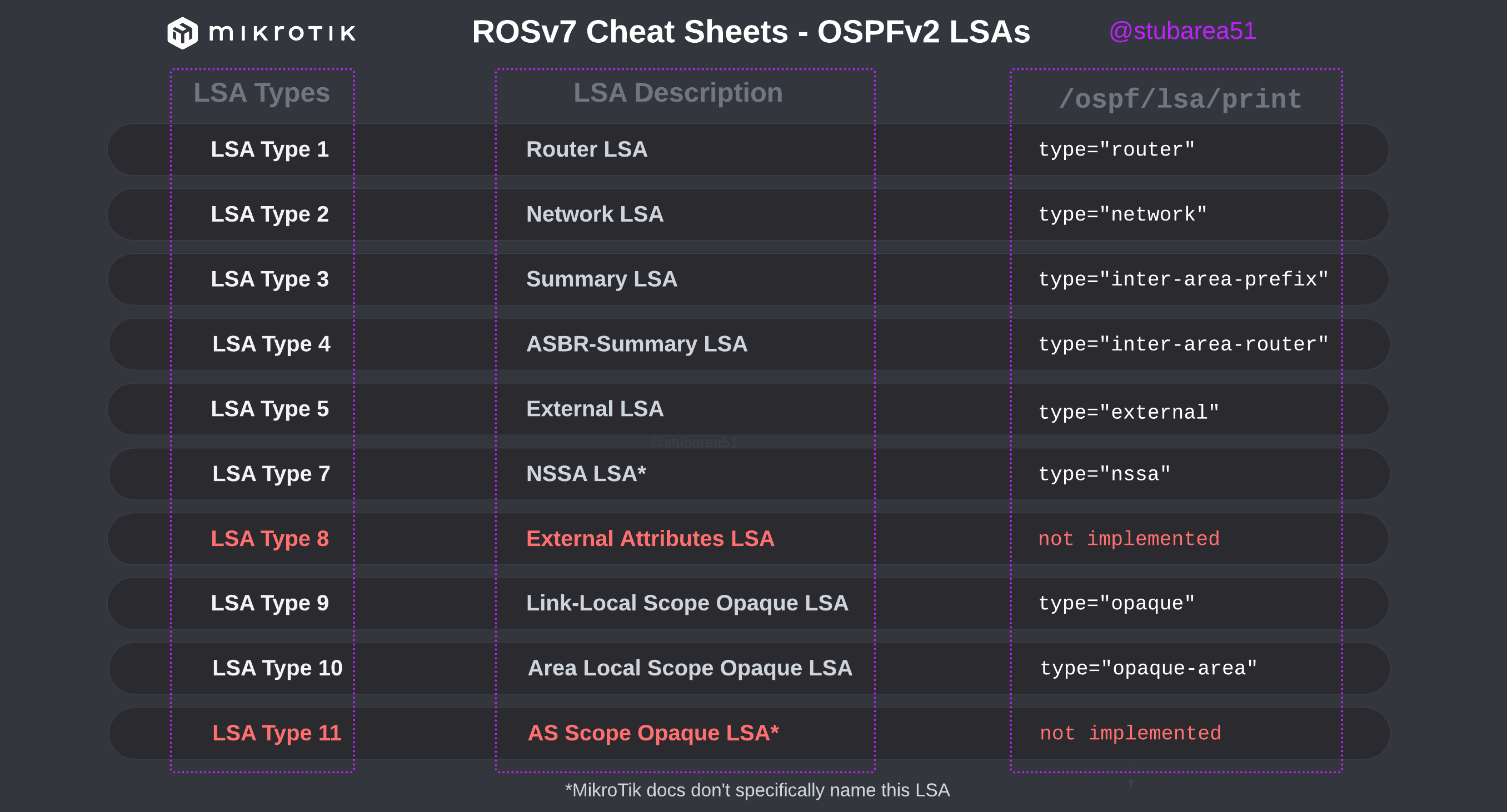
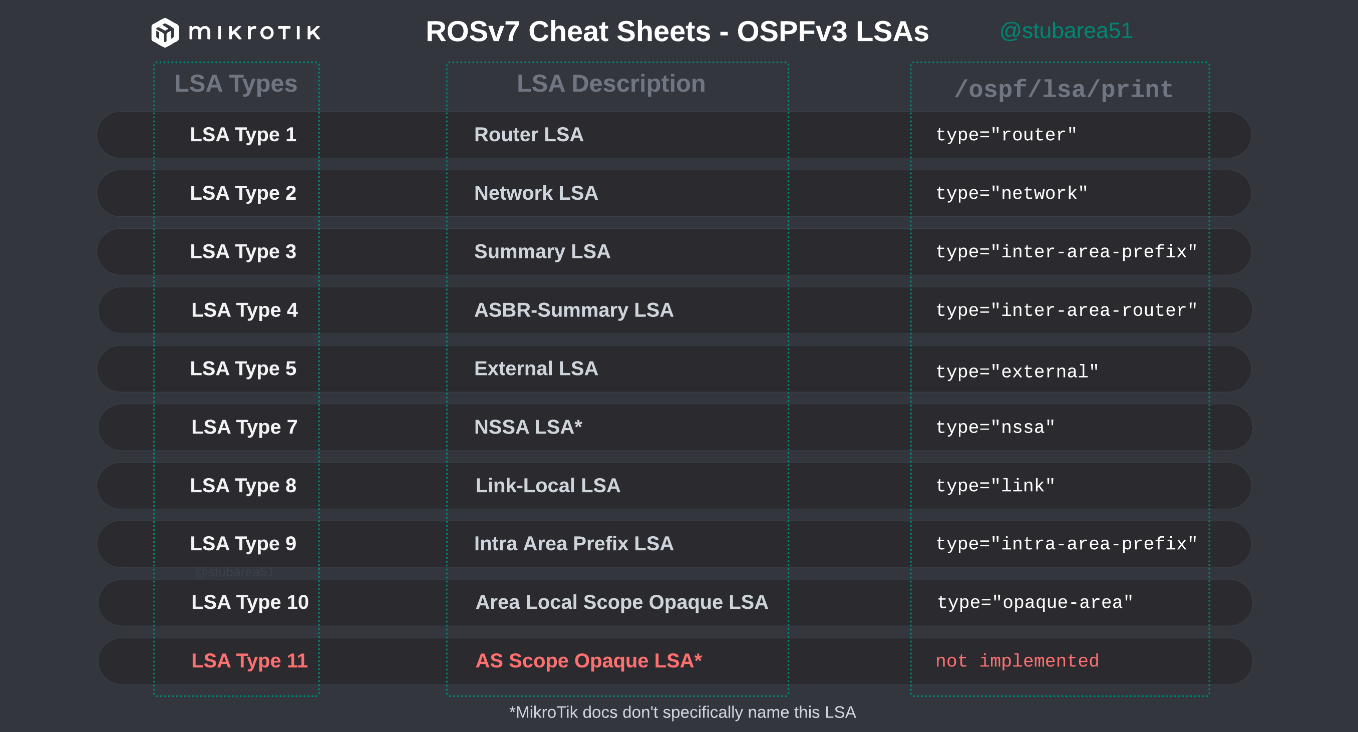
However, MikroTik’s LSA names don’t always match up to the language used in RFCs and other resources when trying to verify the behavior of an LSA is working as intended. This can make troubleshooting difficult.
These cheat sheets match up the lsa description for OSPFv2 and OSPFv3 in RouterOSv7 with the common LSA Type and number reference.
PDF links are listed below – hope you find this helpful!
RouterOS continues to mature as we move through the versions in the teens.
When we transitioned between ROSv5 and ROSv6 in the early 2010s, it was right around this version numbering that we started to see production stability. By the time 6.2x versions came out, the general consensus was that v6 was ready for prime time. We are getting closer to that point in ROSv7 – depending on your use case.
Certainly, there are still issues to solve for advanced users like ISPs and Data Centers that need protocols like BGP, OSPF, IS-IS and MPLS, but simpler use cases seem to really be stabilizing with the last few months of releases.
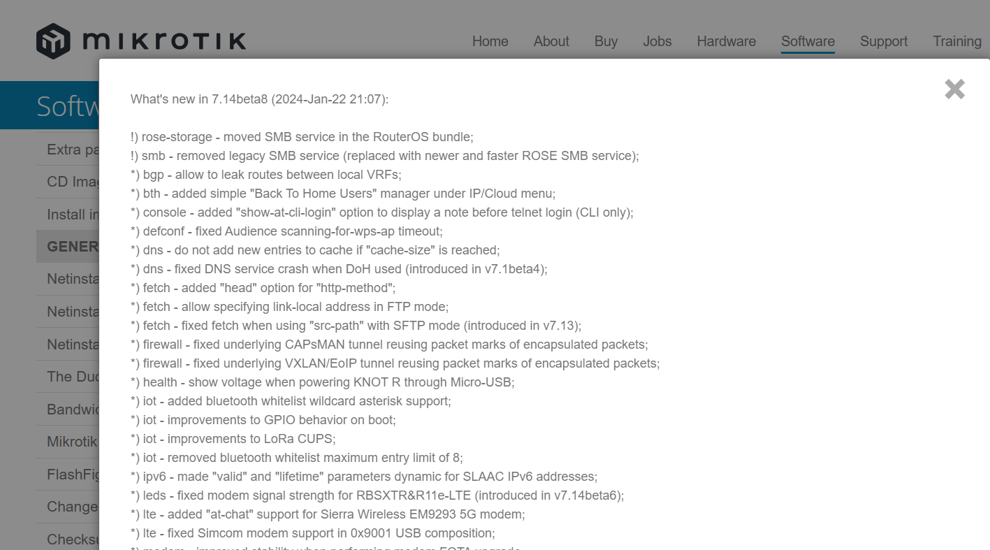
Notable changes in this release:
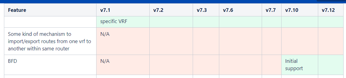
*) bgp – allow to leak routes between local VRFs;
There are a few reasons this is a really important addition to ROSv7. First, it’s an issue that’s been on the roadmap for a very long time as noted in the Routing Protocol Overview section of MikroTik’s help docs. This is encouraging because it’s likely been one of the harder problems for the development team to solve given the length of time it sat open.
Secondly, it’s another step to moving ROSv7 towards better PE, BNG and multi-tenant capabilities. ROSv6 was limited to using only routing rules to leak between routing marks/VRF and overlapping address space inside each VRF was problematic.
Lastly, this paves the way for newer technologies like EVPN, VxLAN (which already exists in ROS) and SR-MPLS – all of which make use of VRFs.
!) smb – removed legacy SMB service (replaced with newer and faster ROSE SMB service);
MikroTik is doubling down on their new ROSE storage package by removing the legacy SMB code and using ROSE as the default.
While mainstream systems/storage engineers are unlikely to flock to MikroTik as an enterprise storage solution, it does open up a world of possibilities when advanced storage services are needed in a small form-factor with minimal power requirements.
Industrial, Manufacturing, Mining and ISPs have frequently used small compute/storage solutions at remote sites or in harsh environments.
It also opens up a lot of possibilities for network automation and management when coupled with the container package.
Unlike mainstream vendors, MikroTik does a phenomenal job of working to keep older hardware relevant and generally does not EOL hardware frequently.
The split in the wireless packages and work to reduce the filesize of the non-Qualcomm package is a good indicator of the commitment to supporting all generations of equipment possible.
*) bth – added simple “Back To Home Users” manager under IP/Cloud menu;
MikroTik seems to be very focused on creating their own “Easy VPN” solution for home/smb users to simplify VPN connectivity.
While ZeroTier and Wireguard are fairly easy to deploy, they do require some advanced config.
It seems like MikroTik is trying to create a simplified version of Tailscale with BTH and it will be interesting to see where it goes.