WISP Design – An overview of adding IPv6 to your WISP

The challenge of adding IPv6 to your WISP

IPv6 is one of those technologies that can feel pretty overwhelming, but it doesn’t have to be. Many of the same ideas and concepts learned in IPv4 networking still apply.

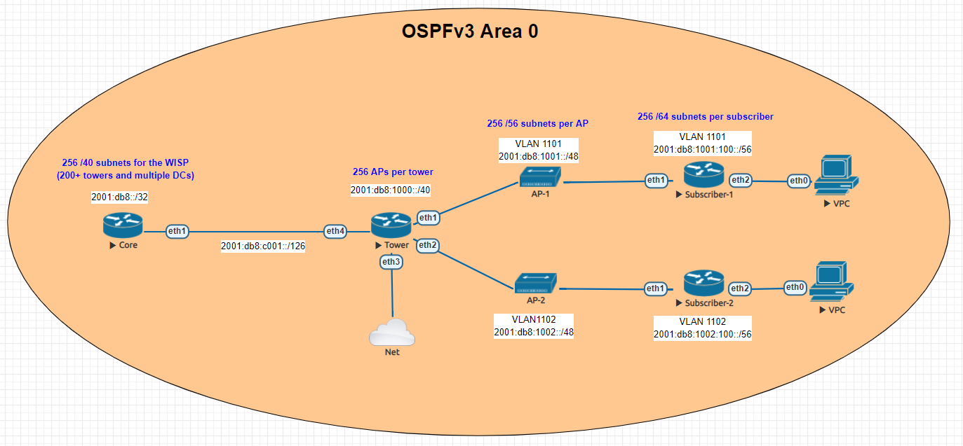
This guide is meant to give you an overview of an example IPv6 addressing plan for an entire WISP as well as the config needed in MikroTik to deploy IPv6 from a core router all the way to a subscriber device.

Benefits of adding IPv6

  • Public addressing for all subscribers – reduced need for NAT
  • Regulatory compliance – public addressing that is persistent makes it much easier to be compliant for things like CALEA
  • Reduced complaints from gamers – Xbox and Playstation both have IPv6 networks and prefer IPv6. This reduces complaints from customers who have gaming consoles that have detected an “improper” NAT configuration.
  • Increased security – IPv6, while not impervious to security threats makes it much harder for attackers to scan IPs due to the sheer size of the IP space. If using privacy extensions with SLAAC, it also makes it much harder to target someone online as the IP address seen on the internet changes randomly.
  • Improved real time communications – one way audio and video issues are often caused by NAT. Using end to end connectivity on public addressing improves the reliability of IP voice and video when used on IPv6
  • Web scale content (Netflix, Facebook, Google, etc) is IPv6 enabled which means a large portion of your traffic will shift to native IPv6 once dual stack is enabled.

IPv6 Addressing

One of the things i’ve learned about IPv6 is that addressing plans seem to spark epic debates about the waste of addresses and what size prefix an end subscriber should get.

Although this lab could have easily been done with a /56 at the tower and /53 at each AP, I decided to use RIPEs recommendations from their guide on IPv6 best operational practices.

This is mainly to keep the focus of the article on actually getting IPv6 deployed and not focusing on the addressing.

Dual Stack

For simplicity, the IPv4 config is not shown, but the recommended design for an operational WISP is to implement IPv4 and IPv6 side by side in a Dual Stack configuration.

Lab Overview

The lab is designed to illustrate most of the operational aspects of IPv6 in a WISP using MikroTik CHR routers in EVE-NG. This includes:

  • DHCPv6 and Prefix Delegation (PD)
  • OSPFv3 single area configuration and origination of a default route
  • Subscriber router example with SLAAC

Core Router

In the lab, the core router is shown directly connected to the tower for simplicity, in your WISP, there may be multiple towers between the core and the end of the network.

The concept, however is the same – use /126 addressing to connect towers for OSPFv3.

Note that OSPFv3 still requires a router-id in dotted decimal format, even though the address you put int doesn’t have to actually exist – for consistency however, use the IPv4 loopback of the router for the router id.

The internet connectivity isn’t shown in this lab, but your ISP will give you a /126 address to connect to your border router and either peer with BGP or the provider can route the /32 prefix to you.

Config

/interface wireless security-profiles
set [ find default=yes ] supplicant-identity=MikroTik
/routing ospf-v3 instance
set [ find default=yes ] distribute-default=always-as-type-1 router-id=\
    100.127.1.1
/ip dhcp-client
add disabled=no interface=ether1
/ipv6 address
add address=2001:db8:c001::1/126 advertise=no interface=ether1
/routing ospf-v3 interface
add area=backbone interface=ether1
/system identity
set name=Core
/tool romon
set enabled=yes

Tower Router

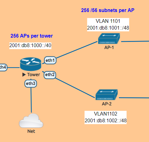
The tower router is handling most of the work as it is responsible for DHCPv6 and Prefix Delegation as well as advertising the /48 AP subnets into OSPF

In this lab , the APs are split into separate VLANs (with dual stack, IPv4 would exist on the same VLAN).

The router is configured to hand out /56 prefixes to the end subscriber using a pool of /48 per AP.

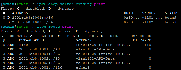
Because Prefix Delegation is being utilized, a dynamic static route is created for each /56 the DHCPv6 server hands out which eliminates the need to use a routing protocol.

Prefix Delegation in action

This example shows the prefixes allocated by the router and the dynamic static routes created

Config

/interface bridge
add name=Lo0
/interface vlan
add interface=ether1 name=vlan1101-AP1-Data vlan-id=1101
add interface=ether2 name=vlan1102-AP2-Data vlan-id=1102
/interface wireless security-profiles
set [ find default=yes ] supplicant-identity=MikroTik
/ipv6 dhcp-server
add address-pool=vl101-v6-pd-pool interface=vlan1101-AP1-Data name=\
    vl101-v6-pd
add address-pool=vl102-v6-pd-pool interface=vlan1102-AP2-Data name=\
    vl102-v6-pd
/ipv6 pool
add comment="VLAN1101 IPv6 prefix delegation pool" name=vl101-v6-pd-pool \
    prefix=2001:db8:1001::/48 prefix-length=56
add comment="VLAN1102 IPv6 prefix delegation pool" name=vl102-v6-pd-pool \
    prefix=2001:db8:1002::/48 prefix-length=56
/routing ospf-v3 instance
set [ find default=yes ] router-id=100.127.1.2
/ip dhcp-client
add disabled=no interface=ether1
/ipv6 address
add address=2001:db8:1001::1/48 advertise=no interface=vlan1101-AP1-Data
add address=2001:db8:1002::1/48 advertise=no interface=vlan1102-AP2-Data
add address=2001:db8:c001::2/126 advertise=no interface=ether4
/ipv6 nd
add interface=vlan1101-AP1-Data managed-address-configuration=yes \
    other-configuration=yes
add interface=vlan1102-AP2-Data managed-address-configuration=yes \
    other-configuration=yes
/ipv6 nd prefix
add autonomous=no interface=vlan1101-AP1-Data
add autonomous=no interface=vlan1102-AP2-Data
/routing ospf-v3 interface
add area=backbone interface=ether4
add area=backbone interface=vlan1101-AP1-Data
add area=backbone interface=vlan1102-AP2-Data
add area=backbone passive=yes
/system identity
set name=Tower
/tool romon
set enabled=yes

Subscriber Routers

For simplicity, MikroTik is used as the Subscriber or CPE router to provide an example of how the /56 prefix is received from the tower router and handed off to devices inside the subscriber’s home.

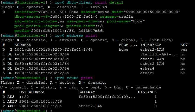
In this lab, the “WAN” interface or ether1 has a DHCPv6 client configured to receive the prefix from the tower router.

Ether2 or the “LAN” side, which would include a bridge of the the wireless/wired interfaces in a real router is configured with a dynamic /64 from the /56 pool and is set for SLAAC to give devices on this segment an IPv6 address.

DHCPv6 client and subscriber addresses/routes

Config – Subscriber 1

/interface ethernet
set [ find default-name=ether1 ] name=ether1-WAN
set [ find default-name=ether2 ] name=ether2-LAN
/interface vlan
add interface=ether1-WAN name=vlan1101-AP1-Data vlan-id=1101
/interface wireless security-profiles
set [ find default=yes ] supplicant-identity=MikroTik
/ip dhcp-client
add disabled=no interface=ether1-WAN
/ipv6 address
add eui-64=yes from-pool=home interface=ether2-LAN
/ipv6 dhcp-client
add add-default-route=yes interface=vlan1101-AP1-Data pool-name=home \
    pool-prefix-length=56 request=prefix
/ipv6 nd
add hop-limit=64 interface=ether2-LAN
/system identity
set name=Subscriber-1
/tool romon
set enabled=yes


Config – Subscriber 2

/interface ethernet
set [ find default-name=ether1 ] name=ether1-WAN
set [ find default-name=ether2 ] name=ether2-LAN
/interface vlan
add interface=ether1-WAN name=vlan1102-AP2-Data vlan-id=1102
/interface wireless security-profiles
set [ find default=yes ] supplicant-identity=MikroTik
/ip dhcp-client
add disabled=no interface=ether1-WAN
/ipv6 address
add eui-64=yes from-pool=home interface=ether2-LAN
/ipv6 dhcp-client
add add-default-route=yes interface=vlan1102-AP2-Data pool-name=home \
    pool-prefix-length=56 request=prefix
/ipv6 nd
add hop-limit=64 interface=ether2-LAN
/system identity
set name=Subscriber-2
/tool romon
set enabled=yes

Subscriber Device

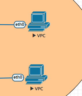
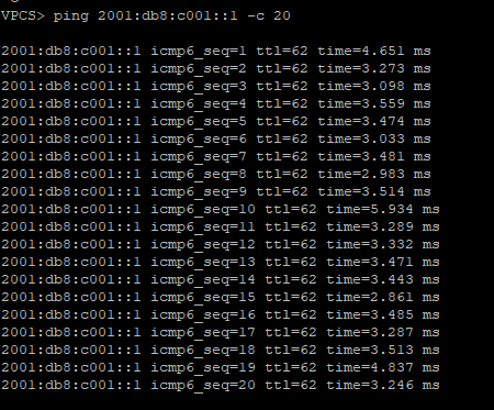
EVE-NG has a small Linux image that can be used as a host called VPC or virtual PC. This allows us to put a device on ether2 and test end to end reachability back to the core router.

SLAAC addressing example

Ping test back to the core router

Success!!!!!!!!

MikroTik ISP Design: Building an 802.1q trunk between sites using VPLS and S-tag

Use Case

ISPs that use MikroTik are always looking for new ways to deliver services to customers and expand their offerings. Delivering Layer 2 at scale for customers is a design challenge that comes up frequently.

While it’s easy enough to build a VLAN nested inside of another VLAN  (see below), this requires you to build all of the VLANs a customer wants to use into the PE router or handoff switch.

However, if you have a client that needs a layer 2 service delivered to two or more points and wants to be able to treat it just like an 802.1q trunk and add VLANs in an ad-hoc way, then using the S-Tag feature in RouterOS along with VPLS transport is a great option.

What’s the S-tag do???

S-Tag

Clients will often ask me “what’s the S-Tag check box for?”

So a little background on this, there is a protocol for using outer and inner VLAN tags specified in IEEE 802.1ad that uses Service Tag (or S-Tag) to denote the outer VLAN tag used to transport Customer Tags (or C-Tags).

What makes the S-Tag/C-Tag a little bit different is that it actually changes the ethertype of the Frame.

ProtocolEthertype
802.1q (Normal VLAN Tags) 0x8100
802.1ad (S-tag) 0x88a8

Here is an overview of the frame format of each and links to the Metro Ethernet Forum Wiki for more info.

S-Tag

https://wiki.mef.net/display/CESG/S-Tag
S-Tag

C-Tag

https://wiki.mef.net/display/CESG/C-Tag

C-Tag

Lab Scenario

Here is a very common example of a deployment for a Layer 2 service to an end customer that rides on top of the ISP MPLS core.

In this lab we are using Cisco switches trunked to each other using VLAN 101 and 201 over a VPLS pseudowire with an S-Tag of 777.

s-tag lab

After configuring the P routers, PE routers and Cisco switches, let’s take a look at the Cisco switch and see if we can ping the SVI on the other switch on both trunked VLANs.

Here are the subnets used on the customer side:

Switch-1 subnets

Now let’s ping the .2 address for each VLAN on Switch-2

VLAN 101

vlan-101-ping

VLAN 201

vlan-201-ping

Notes on MTU

A note on MTU sizing, in order to hand off a 1500 byte packet with VPLS, you normally need an MPLS and L2MTU of 1530 bytes. In order to pass a second VLAN tag you’ll want to make sure your network equipment can go up to 1534 for Layer 2 and MPLS MTUs to pass 1500 byte packet with S-Tag.

Configs for the lab

In the section below, here are all the configs for this deployment

Cisco Switch-1

version 15.2
service timestamps debug datetime msec
service timestamps log datetime msec
no service password-encryption
service compress-config
!
hostname Switch-1
!
boot-start-marker
boot-end-marker
!
!
!
no aaa new-model
!
!
!
!
!
!
!
!
ip cef
no ipv6 cef
!
!
!
spanning-tree mode pvst
spanning-tree extend system-id
!
vlan internal allocation policy ascending
!
!
!
!
!
!
!
!
!
!
!
!
!
!
interface GigabitEthernet0/0
 switchport trunk encapsulation dot1q
 switchport mode trunk
 media-type rj45
 negotiation auto
!
interface GigabitEthernet0/1
 media-type rj45
 negotiation auto
!
interface GigabitEthernet0/2
 media-type rj45
 negotiation auto
!
interface GigabitEthernet0/3
 media-type rj45
 negotiation auto
!
interface GigabitEthernet1/0
 media-type rj45
 negotiation auto
!
interface GigabitEthernet1/1
 media-type rj45
 negotiation auto
!
interface GigabitEthernet1/2
 media-type rj45
 negotiation auto
!
interface GigabitEthernet1/3
 media-type rj45
 negotiation auto
!
interface Vlan101
 description customer-vlan
 ip address 192.168.101.1 255.255.255.0
!
interface Vlan201
 description customer vlan 2
 ip address 192.168.201.1 255.255.255.0
!
ip forward-protocol nd
!
no ip http server
no ip http secure-server
!
!
!
!
!
!
control-plane
!
banner exec ^C
**************************************************************************
* IOSv is strictly limited to use for evaluation, demonstration and IOS  *
* education. IOSv is provided as-is and is not supported by Cisco's      *
* Technical Advisory Center. Any use or disclosure, in whole or in part, *
* of the IOSv Software or Documentation to any third party for any       *
* purposes is expressly prohibited except as otherwise authorized by     *
* Cisco in writing.                                                      *
**************************************************************************^C
banner incoming ^C
**************************************************************************
* IOSv is strictly limited to use for evaluation, demonstration and IOS  *
* education. IOSv is provided as-is and is not supported by Cisco's      *
* Technical Advisory Center. Any use or disclosure, in whole or in part, *
* of the IOSv Software or Documentation to any third party for any       *
* purposes is expressly prohibited except as otherwise authorized by     *
* Cisco in writing.                                                      *
**************************************************************************^C
banner login ^C
**************************************************************************
* IOSv is strictly limited to use for evaluation, demonstration and IOS  *
* education. IOSv is provided as-is and is not supported by Cisco's      *
* Technical Advisory Center. Any use or disclosure, in whole or in part, *
* of the IOSv Software or Documentation to any third party for any       *
* purposes is expressly prohibited except as otherwise authorized by     *
* Cisco in writing.                                                      *
**************************************************************************^C
!
line con 0
line aux 0
line vty 0 4
!
!
end

Cisco Switch-2

version 15.2
service timestamps debug datetime msec
service timestamps log datetime msec
no service password-encryption
service compress-config
!
hostname Switch-2
!
boot-start-marker
boot-end-marker
!
!
!
no aaa new-model
!
!
!
!
!
!
!
!
ip cef
no ipv6 cef
!
!
!
spanning-tree mode pvst
spanning-tree extend system-id
!
vlan internal allocation policy ascending
!
!
!
!
!
!
!
!
!
!
!
!
!
!
interface GigabitEthernet0/0
 switchport trunk encapsulation dot1q
 switchport mode trunk
 media-type rj45
 negotiation auto
!
interface GigabitEthernet0/1
 media-type rj45
 negotiation auto
!
interface GigabitEthernet0/2
 media-type rj45
 negotiation auto
!
interface GigabitEthernet0/3
 media-type rj45
 negotiation auto
!
interface GigabitEthernet1/0
 media-type rj45
 negotiation auto
!
interface GigabitEthernet1/1
 media-type rj45
 negotiation auto
!
interface GigabitEthernet1/2
 media-type rj45
 negotiation auto
!
interface GigabitEthernet1/3
 media-type rj45
 negotiation auto
!
interface Vlan101
 description customer-vlan
 ip address 192.168.101.2 255.255.255.0
!
interface Vlan201
 description customer vlan 2
 ip address 192.168.201.2 255.255.255.0
!
ip forward-protocol nd
!
no ip http server
no ip http secure-server
!
!
!
!
!
!
control-plane
!
banner exec ^C
**************************************************************************
* IOSv is strictly limited to use for evaluation, demonstration and IOS  *
* education. IOSv is provided as-is and is not supported by Cisco's      *
* Technical Advisory Center. Any use or disclosure, in whole or in part, *
* of the IOSv Software or Documentation to any third party for any       *
* purposes is expressly prohibited except as otherwise authorized by     *
* Cisco in writing.                                                      *
**************************************************************************^C
banner incoming ^C
**************************************************************************
* IOSv is strictly limited to use for evaluation, demonstration and IOS  *
* education. IOSv is provided as-is and is not supported by Cisco's      *
* Technical Advisory Center. Any use or disclosure, in whole or in part, *
* of the IOSv Software or Documentation to any third party for any       *
* purposes is expressly prohibited except as otherwise authorized by     *
* Cisco in writing.                                                      *
**************************************************************************^C
banner login ^C
**************************************************************************
* IOSv is strictly limited to use for evaluation, demonstration and IOS  *
* education. IOSv is provided as-is and is not supported by Cisco's      *
* Technical Advisory Center. Any use or disclosure, in whole or in part, *
* of the IOSv Software or Documentation to any third party for any       *
* purposes is expressly prohibited except as otherwise authorized by     *
* Cisco in writing.                                                      *
**************************************************************************^C
!
line con 0
line aux 0
line vty 0 4
!
!
end

MikroTik PE-1

/interface bridge
add name=Lo0
add name=vpls-bridge-vlan-777
/interface vpls
add disabled=no l2mtu=1500 mac-address=02:D5:C2:72:3A:1A name=vpls777 
    pw-type=tagged-ethernet remote-peer=100.127.1.2 vpls-id=8675309:777
/ip neighbor discovery
set ether2 discover=no
/interface vlan
add interface=vpls777 name=vlan777 use-service-tag=yes vlan-id=777
/interface wireless security-profiles
set [ find default=yes ] supplicant-identity=MikroTik
/routing ospf instance
add name=ospf1 router-id=100.127.1.1
/interface bridge port
add bridge=Lo0 interface=ether2
add bridge=Lo0 interface=vlan777
/ip address
add address=100.64.0.1/29 interface=ether1 network=100.64.0.0
add address=100.127.1.1 interface=Lo0 network=100.127.1.1
/ip dhcp-client
add disabled=no interface=ether1
/mpls interface
set [ find default=yes ] mpls-mtu=1534
/mpls ldp
set enabled=yes lsr-id=100.127.1.1 transport-address=100.127.1.1
/mpls ldp interface
add interface=ether1 transport-address=100.127.1.1
/routing ospf network
add area=backbone network=100.64.0.0/29
add area=backbone network=100.127.1.1/32
/system identity
set name=MikroTik-PE-1
/tool romon
set enabled=yes

MikroTik PE-2

/interface bridge
add name=Lo0
add name=vpls-bridge-vlan-777
/interface vpls
add disabled=no l2mtu=1500 mac-address=02:C1:71:EB:0E:E7 name=vpls777 
    pw-type=tagged-ethernet remote-peer=100.127.1.1 vpls-id=8675309:777
/ip neighbor discovery
set ether2 discover=no
/interface vlan
add interface=vpls777 name=vlan777-s-tag use-service-tag=yes vlan-id=777
/interface wireless security-profiles
set [ find default=yes ] supplicant-identity=MikroTik
/routing ospf instance
add name=ospf1 router-id=100.127.1.2
/interface bridge port
add bridge=Lo0 interface=vlan777-s-tag
add bridge=Lo0 interface=ether2
/ip address
add address=100.64.0.18/29 interface=ether1 network=100.64.0.16
add address=100.127.1.2 interface=Lo0 network=100.127.1.2
/ip dhcp-client
add dhcp-options=hostname,clientid disabled=no interface=ether1
/mpls interface
set [ find default=yes ] mpls-mtu=1534
/mpls ldp
set enabled=yes lsr-id=100.127.1.2 transport-address=100.127.1.2
/mpls ldp interface
add interface=ether1 transport-address=100.127.1.2
/routing ospf network
add area=backbone network=100.64.0.16/29
add area=backbone network=100.127.1.2/32
/system identity
set name=MikroTik-PE-2
/tool romon
set enabled=yes

MikroTik P-CORE-1

/interface bridge
add name=Lo0
/interface vlan
add interface=ether1 name=vlan101 vlan-id=777
/interface wireless security-profiles
set [ find default=yes ] supplicant-identity=MikroTik
/routing ospf instance
set [ find default=yes ] router-id=100.127.0.1
/ip address
add address=100.64.0.2/29 interface=ether1 network=100.64.0.0
add address=100.127.0.1 interface=Lo0 network=100.127.0.1
add address=100.64.0.9/29 interface=ether2 network=100.64.0.8
/ip dhcp-client
add dhcp-options=hostname,clientid disabled=no interface=ether1
/mpls interface
set [ find default=yes ] mpls-mtu=1534
/mpls ldp
set enabled=yes lsr-id=100.127.0.1 transport-address=100.127.0.1
/mpls ldp interface
add interface=ether1 transport-address=100.127.0.1
add interface=ether2 transport-address=100.127.0.1
/routing ospf network
add area=backbone network=100.64.0.0/29
add area=backbone network=100.127.0.1/32
add area=backbone network=100.64.0.8/29
/system identity
set name=MikroTik-P-Core-1
/tool romon
set enabled=yes

MikroTik P-CORE-2

/interface bridge
add name=Lo0
/interface wireless security-profiles
set [ find default=yes ] supplicant-identity=MikroTik
/routing ospf instance
set [ find default=yes ] router-id=100.127.0.2
/ip address
add address=100.64.0.10/29 interface=ether1 network=100.64.0.8
add address=100.127.0.2 interface=Lo0 network=100.127.0.2
add address=100.64.0.17/29 interface=ether2 network=100.64.0.16
/ip dhcp-client
add dhcp-options=hostname,clientid disabled=no interface=ether1
/mpls interface
set [ find default=yes ] mpls-mtu=1534
/mpls ldp
set enabled=yes lsr-id=100.127.0.2 transport-address=100.127.0.2
/mpls ldp interface
add interface=ether1 transport-address=100.127.0.2
add interface=ether2 transport-address=100.127.0.2
/routing ospf network
add area=backbone network=100.64.0.8/29
add area=backbone network=100.127.0.2/32
add area=backbone network=100.64.0.16/29
/system identity
set name=MikroTik-P-Core-2
/tool romon