Let’s talk MPLS-VPLS, part 1 – use cases

Hey guys, today we’ll be taking a look at what are the main reasons that MPLS – and in particular VPLS – is a useful technology tool to get traffic from point A to point Z. There’s really 2 major use cases that I deal with regularly: IPv4 conservation and L2VPN.

Why am I talking about VPLS specifically? Well, mostly because many times I end up working with Mikrotik routers, which only support VPLS. What is VPLS? It stands for Virtual Private Line Service, and it’s a way to deliver layer 2 services over a layer 3 network. Said another way, it connects a single broadcast domain to multiple endpoints across a routed network. I’ll discuss why MPLS is better for you and your network than switching/bridging in part 2 of this series – for now just know that MPLS/VPLS will allow you to offer enhanced services without the risks of extending layer 2 (I’ll talk more about that below, and why that’s bad in part 2, also).


Use case 1: IPv4 Conservation

OK, so let’s visualize the problem with IP conservation on a small /24 allocation.

Subnetted /24 network

If you’re like most other service providers, you have a limited capacity of IPv4 and constantly using subnetting to carve out IP space for various locations. Inevitably, you end up needing a bigger network somewhere (like A) and in other places you’ve allocated too many IPs and they’re going wasted and unused (like B). Not to mention, with subnetting we’re forced to burn a network ID and broadcast each time we pull out the network scalpel – ouch!

As you can see, in this network, subnetting has resulted in 16 IPs used for IDs and subnets, 8 more for gateways, and over in area B let’s say there’s 37 unassigned IPs – that’s 60 IPs out of 254 that customers can’t use, almost 25% of this expensive revenue generating resource is tied up!

Here’s a solution based on MPLS/VPLS that efficiently leverages the entire /24 allocation:

/24 used efficiently with VPLS

Now we’re only using 1 network ID, 1 broadcast, and 1 gateway for our /24. The entire rest of the allocation can be delivered to any endpoint that’s connected the MPLS cloud – leaving 253 addresses available for customer assignments! And growth can happen at any tower – we no longer have to care which customers are on which tower, and how much IP space is available at the tower layer.

Compared to the above scenario, our IP allocation overhead went down from 25% to just over 1%! Now that’s efficient use of IPv4 space.


https://iparchitechs.com/contact


Use case 2: L2VPN

Connecting multiple offices across a service provider network can often be a very lucrative way to offer transparent LAN service to customers. The reason we call it transparent is because it allows whatever customer traffic is input in one end of the network to be seen at another end of the network. In a typical routed network, BUM traffic (which I’ll cover more in part 2) gets isolated at layer 3, routed boundaries. With VPLS, your network gets the full benefits of the layer 3 boundaries, and your customer gets the connectivity benefits of being connected layer 2!

Some of the more common customers looking for a L2VPN service include government, energy and banks. But really, any customer who’d like to connect the same subnet at several different physical locations that are served by different equipment across your network are a great candidates. Sometimes they’d like to pass their own VLAN traffic, other times they need multicast for a video conferencing application, or even something as simple as a small network with only 1 DHCP server / firewall / internet gateway and they want to force all traffic through that central point. Regardless of the reason, this premium service can bring in great revenue.

Can’t I just provide L2 service by extending a VLAN? Absolutely, you can. Should I just extend my bridged/switched network to provide this service? NO! You should absolutely avoid this as much as possible! As we’ll see in part 2, isolating fault domains and adding L3 boundaries are key to protecting your network from bad days.

Let’s see an example:

Don’t bridge to customers

Here, we’ve extended the network using bridging and switching (L2) constructs to connect customer locations A B and C. When we have a bad day on this network, the scope of our network meltdown includes the entirety of ALL the gear and ALL our customers. Ouch!

Whether it’s a customer introduced loop, infected customer device, or a customer host spewing garbage onto to their network, there’s no protection between the customer edge (CE) and provider edge (PE) and no boundaries to stop that bad traffic.

Fortunately, there’s a better way:

Friends don’t let friends bridge networks

With MPLS/VPLS, you can see that the scope of our outage is isolated to the customer edge (the port handoff to A, B, and C), or at worst only the VPLS router endpoints, depending on the gear, QoS policies, and configuration. Now, a bad day on the customer’s network isn’t necessarily a bad day for our service provider network.


I hope you enjoyed this article and keep an eye out for part 2 where I’ll talk more in depth about L2 (bridging/switching) vs L3 (routing) and why MPLS/VPLS is referred to as layer 2.5.

Put 500,000+ BGP routes in your lab network!!! Download this VM and become your own upstream BGP ISP for testing.

[adrotate banner=”5″]


Happy New Year and welcome to the VM you can punish your routers with 🙂

Hello from stubarea51.net and Happy New Year! We are back from the holidays and recharged with lots of new stuff in the world of network engineering. If you ever thought it would be cool to put a full BGP table into a lab router, GNS3 or other virtualized router, you’re not alone.

A while back, I tackled this post and got everything up and running:

http://evilrouters.net/2009/08/21/getting-bgp-routes-into-dynamips-with-video/

First of all, thanks to evilrouters.net for figuring out the hard parts so we could build this into a VM. After basking for a while in the high geek factor of this project, it gave me an idea to build a VM that could be distributed among network engineers and IT professionals. The idea is to easily spin up one or more full BGP tables to test a particular network design or convergence speed, playing with BGP attributes, etc. After a few months of tweaking it and getting the VM ready for distribution, we finally are ready to put it out for everyone to use.

Network Diagram

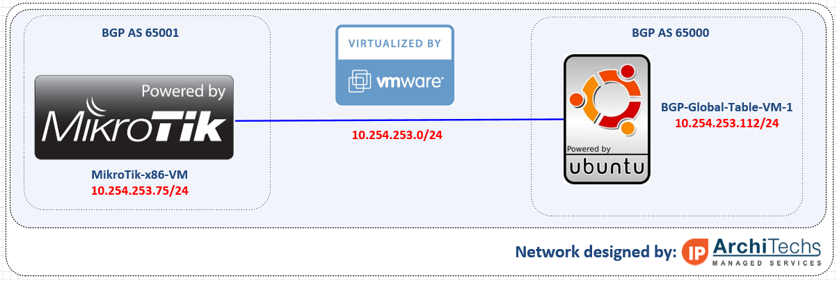
Here is an overview of the topology we used for testing our full BGP table. This can be done a number of different ways and you can use just about any combination of Hypervisors including VM Ware and VirtualBox which are the two downloads included in this post. In this setup, we are using a MikroTik x86 VM to peer into the Ubuntu VM that has copies of the global table. It established an EBGP peering over 10.254.253.0/24 and takes in a full table.

BGP-VM-Network-Diagram

Getting started 

First you need to download either the VM Ware or VirtualBox OVA files and import them into your hypervisor. The setup and installation of VM Ware ESXi or VirtualBox is beyond the scope of this post, so please google it if you need help.

Downloads

Download .OVA for VM Ware

Download .OVA for VirtualBox

Powering up the VM

Once you have successfully imported the VM, you will get a screen that looks like this:
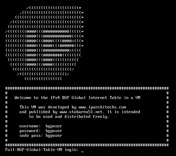
BGP-VM-Startup-page

Credentials

Here are the credentials which you can change if needed.

username: bgpuser

password: bgpuser

sudo password: bgpuser

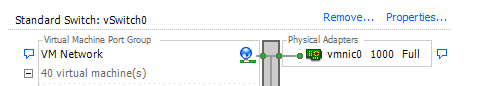
Bridging the VM NIC to your lab network

In order to have IP connectivity to another router (physical or virtual) you will need to setup the VM NIC to connect to the network you want to test on. There are a number of different ways to connect VMs into a virtual or physical network.

VM Ware – we connected the VM to the default VM management network (which is a physical server NIC) so it could reach other VMs and physical lab routers

ESXi-vswitch


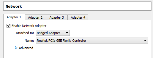
VirtualBox – we bridged the VM to the NIC of the desktop we are running VirtualBox on so it could reach other VMs and physical lab routers

VirtualBox-network-bridged

BGP Feeds that are used in this VM

The BGP feeds that are available come from the RIPE RIS Raw Data page and were archived in January 2016. We included 6 different tables from 4 continents so you can have up to 6 unique BGP tables to use in your lab testing. See the next section for the syntax to use for one of these files.

RIPE RRCFile Name
rrc00.ripe.netISP1-Europe-Amsterdam-Jan-2016
rrc01.ripe.netISP2-Europe-London-Jan-2016
rrc06.ripe.netISP3-Asia-Tokyo-Jan-2016
rrc15.ripe.netISP4-SouthAmerica-SaoPaulo-Jan-2016
rrc11.ripe.netISP5-NorthAmerica-NewYork-Jan-2016
rrc14.ripe.netISP6-NorthAmerica-PaloAlto-Jan-2016

Important Note !!!! – Using this VM does not provide connectivity to the Internet and will likely cause an outage when connected to a production network with live BGP peerings. This VM is intended to simulate an upstream peering for testing and lab development.

Setting up a BGP peering – BGP VM

Once you have IP connectivity and can ping the router you want to peer with, you can set up a peering on the VM. Here is the command syntax – first change to the bgp directory and issue the command below (with edits for your IPs and AS numbers)

[email protected]:~$ cd bgp
[email protected]:~/bgp$ sudo ./bgp_simple.pl -myas 65000 -myip 10.254.253.112 -peerip 10.254.253.75 -peeras 65051 -p ISP1-Europe-Amsterdam-Jan-2016

Options for the BGP Peering (using the program bgp_simple ver 0.12)

[email protected]:~/bgp$ ./bgp_simple.pl

Please provide -myas, -myip, -peerip and -peeras!

bgp_simple.pl: Simple BGP peering and route injection script.
Version v0.12, 22-Jan-2011.

usage:
bgp_simple.pl:
                -myas           ASNUMBER        # (mandatory) our AS number
                -myip           IP address      # (mandatory) our IP address to source the sesion from
                -peerip         IP address      # (mandatory) peer IP address
                -peeras         ASNUMBER        # (mandatory) peer AS number
                [-holdtime]     Seconds         # (optional) BGP hold time duration in seconds (default 60s)
                [-keepalive]    Seconds         # (optional) BGP KeepAlive timer duration in seconds (default 20s)
                [-nolisten]                     # (optional) dont listen at $myip, tcp/179
                [-v]                            # (optional) provide verbose output to STDOUT, use twice to get debugs
                [-p file]                       # (optional) prefixes to advertise (bgpdump formatted)
                [-o file]                       # (optional) write all sent and received UPDATE messages to file
                [-m number]                     # (optional) maximum number of prefixes to advertise
                [-n IP address]                 # (optional) next hop self, overrides original value
                [-l number]                     # (optional) set default value for LOCAL_PREF
                [-dry]                          # (optional) dry run; dont build adjacency, but check prefix file (requires -p)
                [-f KEY=REGEX]                  # (optional) filter on input prefixes (requires -p), repeat for multiple filters
                                                        KEY is one of the following attributes (CaSE insensitive):

                                                        NEIG            originating neighbor
                                                        NLRI            NLRI/prefix(es)
                                                        ASPT            AS_PATH
                                                        ORIG            ORIGIN
                                                        NXHP            NEXT_HOP
                                                        LOCP            LOCAL_PREF
                                                        MED             MULTI_EXIT_DISC
                                                        COMM            COMMUNITY
                                                        ATOM            ATOMIC_AGGREGATE
                                                        AGG             AGGREGATOR

                                                        REGEX is a perl regular expression to be expected in a
                                                        match statement (m/REGEX/)

Without any prefix file to import, only an adjacency is established and the received NLRIs, including their attributes, are logged.

Setting up a BGP peering – Your peering router

We used a MikroTik x86 VM in ESXi for this test, but any brand of virtual or physical router that supports BGP can be used.

[[email protected]] > routing bgp export          
# jan/21/2016 10:34:43 by RouterOS 6.30.1
# software id = KC33-08AQ
#
/routing bgp instance
set default as=65001
/routing bgp peer
add hold-time=30m keepalive-time=4m15s name=BGP-VM remote-address=10.254.253.112 remote-as=65000 ttl=default

Sit back and watch hundreds of thousands of prefixes torture the CPU of your router

MikroTik-VM-500k-routes