What is VPLS?
Virtual Private LAN Service or VPLS is a Layer 2 overlay or tunnel that allows for the encapsulation of ethernet frames (with or without VLAN tags) over an MPLS network.
https://tools.ietf.org/html/rfc4762
VPLS is often found in Telco networks that rely on PPPoE to create centralized BRAS deployments by bringing all of the end users to a common point via L2.
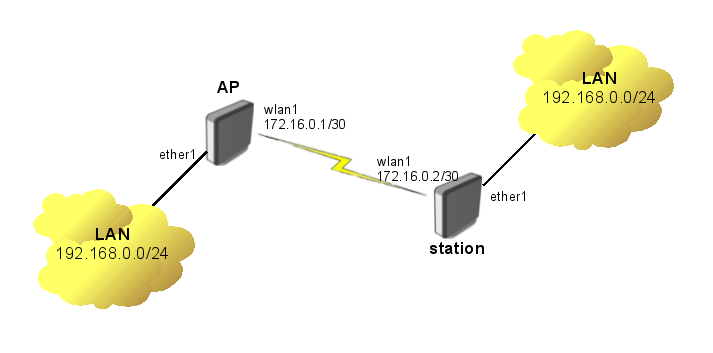
MikroTik VPLS example (https://wiki.mikrotik.com/wiki/Transparently_Bridge_two_Networks_using_MPLS)
Background
The idea for this post came out of a working session (at the bar of course) at WISPAmerica 2018 in Birmingham, Alabama.
There was a discussion about how to create redundancy for VPLS tunnels on multiple routers. I started working on this in EVE-NG as we were talking about it.
The goal is creating highly available endpoints for VPLS when using them to deploy a public subnet that can be delivered to any tower in the WISP. The same idea works for wireline networks as well.
Use Case
As IPv4 becomes harder to get, ISPs like WISPs, without large blocks of public space find it difficult to deploy them in smaller subnets. The idea behind breaking up a /23 or /24 for example, is that every tower has public IP addresses available.
However, the problem with this approach is that some subnets may not be used if there isn’t much demand for a dedicated public IP by customers.
What makes VPLS attractive in this scenario is that the public subnet (a /24 in this example) can be placed at the data center as an intact prefix.
VPLS tunnels then allow for individual IP addresses to exist at any tower in the network which provides flexibility and conserves IPv4 space by not subnetting the block into /29 /28 /27 at the tower level.
Lab Network
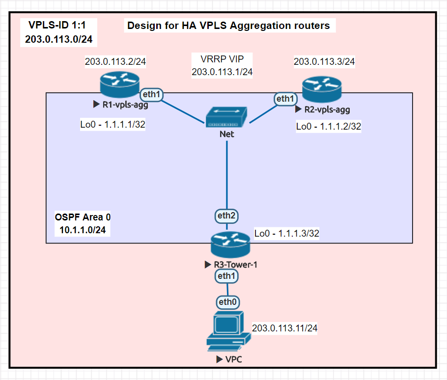
Deployment
In this lab, the VPLS tunnels terminate in two different data centers as well as at a tower router to create an L2 segment for 203.0.113.0/24. VRRP is then run between the two data center VPLS routers so that the gateway of 203.0.113.1 can failover to the other DC if needed.
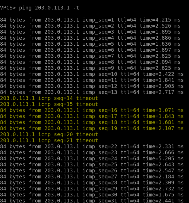
Failover
Here is an example of the convergence time when we manually fail R1 and the gateway flips over to R2 in the other DC. The yellow highlight marks the point where R1 has failed and R2 VRRP has become master.
Configurations
R1-vpls-agg
/interface bridge
add name=Lo0
add name=vpls1-1
/interface vrrp
add interface=vpls1-1 name=vpls1-1-vrrp priority=200
/interface vpls
add disabled=no l2mtu=1500 mac-address=02:2C:0B:61:64:CB name=vpls1 remote-peer=1.1.1.2 vpls-id=1:1
add disabled=no l2mtu=1500 mac-address=02:7C:8C:C9:CE:8E name=vpls2 remote-peer=1.1.1.3 vpls-id=1:1
/interface wireless security-profiles
set [ find default=yes ] supplicant-identity=MikroTik
/interface bridge port
add bridge=vpls1-1 interface=vpls1
add bridge=vpls1-1 interface=vpls2
/ip address
add address=1.1.1.1 interface=Lo0 network=1.1.1.1
add address=10.1.1.1/24 interface=ether1 network=10.1.1.0
add address=203.0.113.2/24 interface=vpls1-1 network=203.0.113.0
add address=203.0.113.1/24 interface=vpls1-1-vrrp network=203.0.113.0
/ip dhcp-client
add disabled=no interface=ether1
/mpls ldp
set enabled=yes lsr-id=1.1.1.1 transport-address=1.1.1.1
/mpls ldp interface
add interface=ether1
/routing ospf network
add area=backbone network=10.1.1.0/24
add area=backbone network=1.1.1.1/32
/system identity
set name=R1-vpls-agg
R2-vpls-agg
/interface bridge
add name=Lo0
add name=vpls1-1
/interface vrrp
add interface=vpls1-1 name=vpls1-1-vrrp
/interface vpls
add disabled=no l2mtu=1500 mac-address=02:C3:4C:31:FB:C9 name=vpls1 remote-peer=1.1.1.1 vpls-id=1:1
add disabled=no l2mtu=1500 mac-address=02:02:34:C0:A3:3C name=vpls2 remote-peer=1.1.1.3 vpls-id=1:1
/interface wireless security-profiles
set [ find default=yes ] supplicant-identity=MikroTik
/interface bridge port
add bridge=vpls1-1 interface=vpls1
add bridge=vpls1-1 interface=vpls2
/ip address
add address=10.1.1.2/24 interface=ether1 network=10.1.1.0
add address=1.1.1.2 interface=Lo0 network=1.1.1.2
add address=203.0.113.3/24 interface=vpls1-1 network=203.0.113.0
add address=203.0.113.1/24 interface=vpls1-1-vrrp network=203.0.113.0
/ip dhcp-client
add disabled=no interface=ether1
/mpls ldp
set enabled=yes lsr-id=1.1.1.2 transport-address=1.1.1.2
/mpls ldp interface
add interface=ether1
/routing ospf network
add area=backbone network=10.1.1.0/24
add area=backbone network=1.1.1.2/32
/system identity
set name=R2-vpls-agg
R3-Tower-1
/interface bridge
add name=Lo0
add name=vpls-1-1
/interface vpls
add disabled=no l2mtu=1500 mac-address=02:CB:47:7A:92:0B name=vpls1 remote-peer=1.1.1.1 vpls-id=1:1
add disabled=no l2mtu=1500 mac-address=02:E3:C5:5B:EC:BF name=vpls2 remote-peer=1.1.1.2 vpls-id=1:1
/interface wireless security-profiles
set [ find default=yes ] supplicant-identity=MikroTik
/interface bridge port
add bridge=vpls-1-1 interface=ether1
add bridge=vpls-1-1 interface=vpls1
add bridge=vpls-1-1 interface=vpls2
/ip address
add address=10.1.1.3/24 interface=ether2 network=10.1.1.0
add address=1.1.1.3 interface=Lo0 network=1.1.1.3
/ip dhcp-client
add disabled=no interface=ether1
/mpls ldp
set enabled=yes lsr-id=1.1.1.3 transport-address=1.1.1.3
/mpls ldp interface
add interface=ether2
/routing ospf network
add area=backbone network=10.1.1.0/24
add area=backbone network=1.1.1.3/32
/system identity
set name=R3-tower-vpls