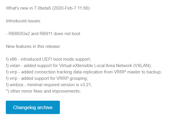
VxLAN support added in 7.0beta5
MikroTik announced VxLAN support on Valentine’s Day (Feb 14th) of 2020.
This is a significant feature addition for RouterOSv7 as it will pave the way for a number of other additions like EVPN in BGP.
It will also give MikroTik the ability to appeal to enterprises and data centers that might need cost-effective VxLAN capable devices.
Service Providers are also moving towards VxLAN as a future replacement for VPLS so this is helpful for that market as well.
Download the OVA here:
https://download.mikrotik.com/routeros/7.0beta5/chr-7.0beta5.ova
Implementation
The initial release of VxLAN is based on unicast and multicast to deliver Layer 2 frames.
As there is no EVPN support, the VTEPs must be manually configured for each endpoint in a full mesh configuration.
The VxLAN interface can then be bridged to a physical ethernet port or VLAN interface to deliver the traffic to the end host.
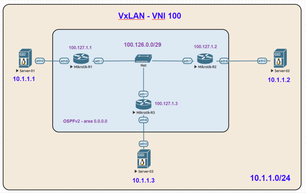
Lab Example
Here is an overview lab in EVE-NG with a basic setup using 3 linux servers on the same 10.1.1.0/24 subnet which is carried as an overlay by VxLAN.
VxLAN reachability for VTEPs is acheived with OSPFv2 and loopback addresses.
VNI: 100
Multicast Group: 239.0.0.1
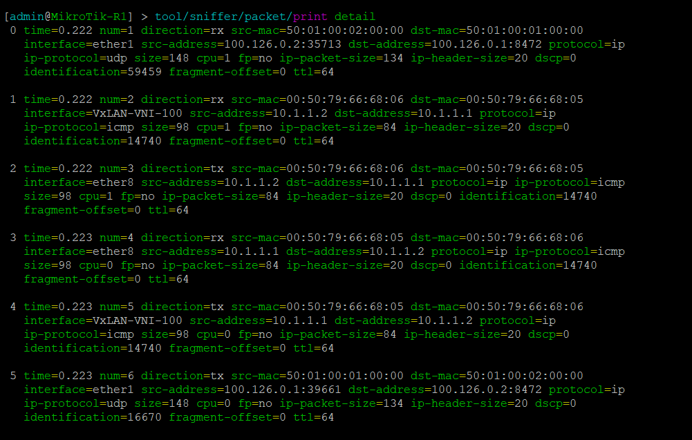
Lab Validation
In the following packet capture, traffic to UDP port 8472 can be seen between two endpoints.
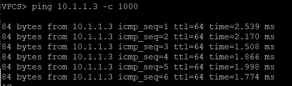
The ICMP ping test between server 1 (10.1.1.1) and server 2 (10.1.1.2) is also visible
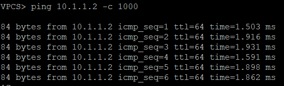
Pings between Server 1 and Servers 2 & 3
Configurations
R1
/interface bridge
 add name=Bridge-VxLAN-VNI-100
 add name=Lo0
 /interface vxlan
 add group=239.0.0.1 interface=ether1 mtu=1400 name=VxLAN-VNI-100 port=8472 vni=100
 /routing ospf instance
 add name=ospf-instance-1 router-id=100.127.1.1 version=2
 /routing ospf area
 add area-id=0.0.0.0 instance=ospf-instance-1 name=ospf-area-1
 /interface bridge port
 add bridge=Bridge-VxLAN-VNI-100 interface=ether8
 add bridge=Bridge-VxLAN-VNI-100 interface=VxLAN-VNI-100
 /interface vxlan vteps
 add interface=VxLAN-VNI-100 remote-ip=100.127.1.2
 add interface=VxLAN-VNI-100 remote-ip=100.127.1.3
 /ip address
 add address=100.127.1.1 interface=Lo0 network=100.127.1.1
 add address=100.126.0.1/29 interface=ether1 network=100.126.0.0
 /routing ospf interface
 add area=ospf-area-1 instance-id=0 network=100.126.0.0/29
 add area=ospf-area-1 instance-id=0 network=100.127.1.1
 /system identity
 set name=MikroTik-R1
R2
/interface bridge
 add name=Bridge-VxLAN-VNI-100
 add name=Lo0
 /interface vxlan
 add group=239.0.0.1 interface=ether1 mtu=1400 name=VxLAN-VNI-100 port=8472    vni=100
 /routing ospf instance
 add name=ospf-instance-1 router-id=100.127.1.2 version=2
 /routing ospf area
 add area-id=0.0.0.0 instance=ospf-instance-1 name=ospf-area-1
 /interface bridge port
 add bridge=Bridge-VxLAN-VNI-100 interface=ether8
 add bridge=Bridge-VxLAN-VNI-100 interface=VxLAN-VNI-100
 /interface vxlan vteps
 add interface=VxLAN-VNI-100 remote-ip=100.127.1.1
 add interface=VxLAN-VNI-100 remote-ip=100.127.1.3
 /ip address
 add address=100.127.1.2 interface=Lo0 network=100.127.1.2
 add address=100.126.0.2/29 interface=ether1 network=100.126.0.0
 /routing ospf interface
 add area=ospf-area-1 instance-id=0 network=100.126.0.0/29
 add area=ospf-area-1 instance-id=0 network=100.127.1.2
 /system identity
 set name=MikroTik-R2
R3
 /interface bridge
 add name=Bridge-VxLAN-VNI-100
 add name=Lo0
 /interface vxlan
 add group=239.0.0.1 interface=ether1 mtu=1400 name=VxLAN-VNI-100 port=8472
     vni=100
 /routing ospf instance
 add name=ospf-instance-1 router-id=100.127.1.3 version=2
 /routing ospf area
 add area-id=0.0.0.0 instance=ospf-instance-1 name=ospf-area-1
 /interface bridge port
 add bridge=Bridge-VxLAN-VNI-100 interface=ether8
 add bridge=Bridge-VxLAN-VNI-100 interface=VxLAN-VNI-100
 /interface vxlan vteps
 add interface=VxLAN-VNI-100 remote-ip=100.127.1.1
 add interface=VxLAN-VNI-100 remote-ip=100.127.1.2
 /ip address
 add address=100.127.1.3 interface=Lo0 network=100.127.1.3
 add address=100.126.0.3/29 interface=ether1 network=100.126.0.0
 /routing ospf interface
 add area=ospf-area-1 instance-id=0 network=100.126.0.0/29
 add area=ospf-area-1 instance-id=0 network=100.127.1.3
 /system identity
 set name=MikroTik-R3