Introduction
One challenge that every WISP owner or operator has faced is how to leverage unused bandwidth on a backup path to generate more revenue.
For networks that have migrated to MPLS and BGP, this is an easier problem to solve as there are tools that can be used in those protocols like communities or MPLS TE to help manage traffic and set policy.
However, many WISPs rely solely on OSPF and cost adjustment to attempt to influence traffic. Alternatively, trying to use policy routing can lead to a design that doesn’t failover or scale well.
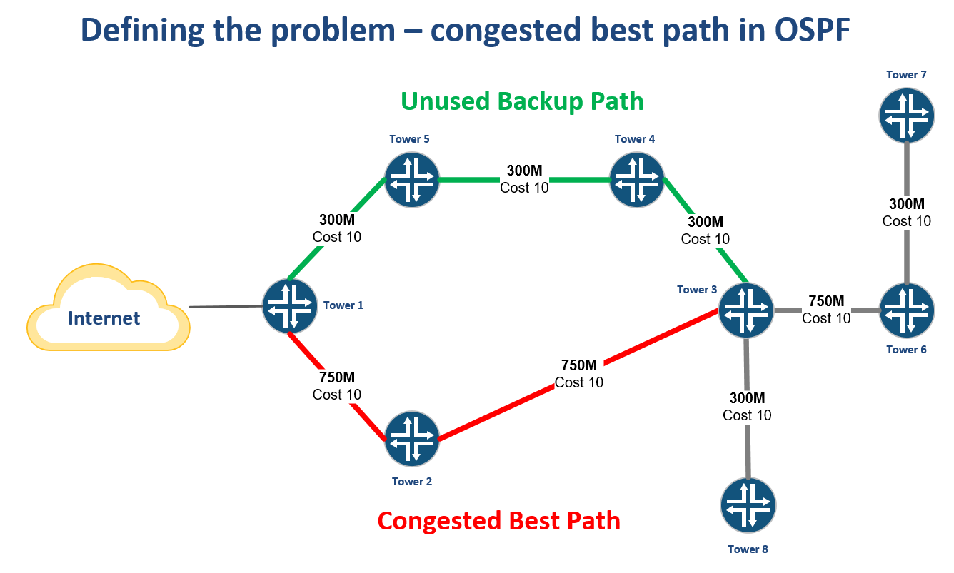
Creating a bottleneck on a single path
WISPs that are OSPF routed will often have a primary path back to the Internet at one or more points in the network typically from a tower that aggregates multiple backhauls.
As more towers are added that rely on this path, it can create a bottleneck while other paths are unused.
Creating an alternate best path by leapfrogging another router
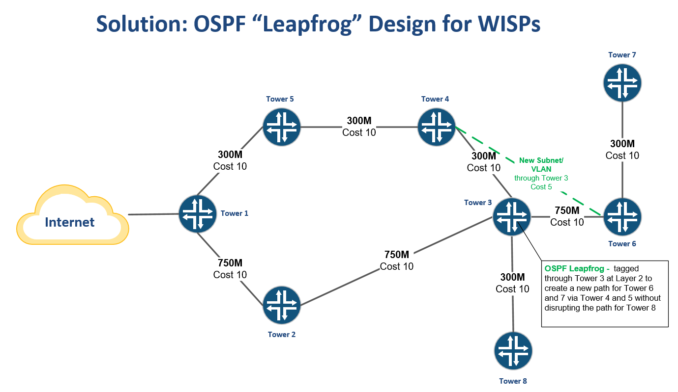
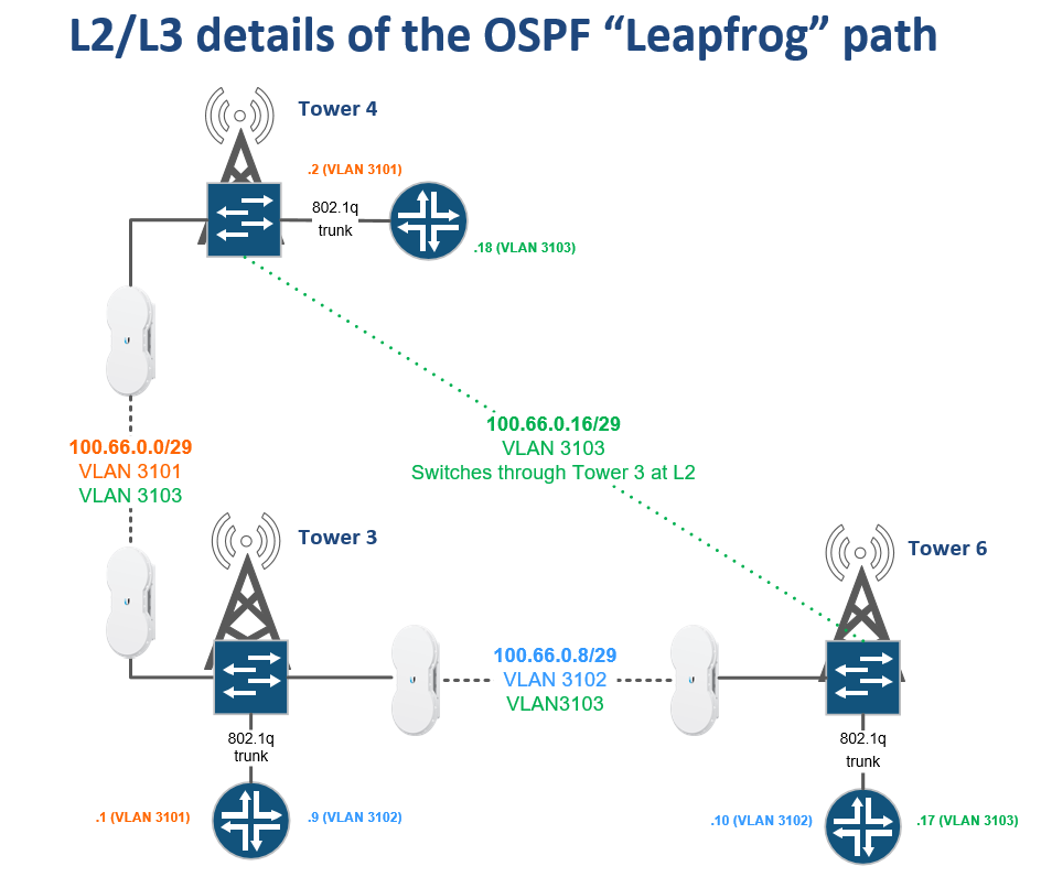
One way to solve this problem is to use VLANs to create another subnet for OSPF to form an adjacency.
By tagging the VLAN from Tower 6 through Tower 3 and into Tower 4, a new path for OSPF is created that will cause Tower 6 and Tower 7 to take an alternate path.
This allows a WISP operator to tap into unused bandwidth while still retaining a straightforward failover mechanism.
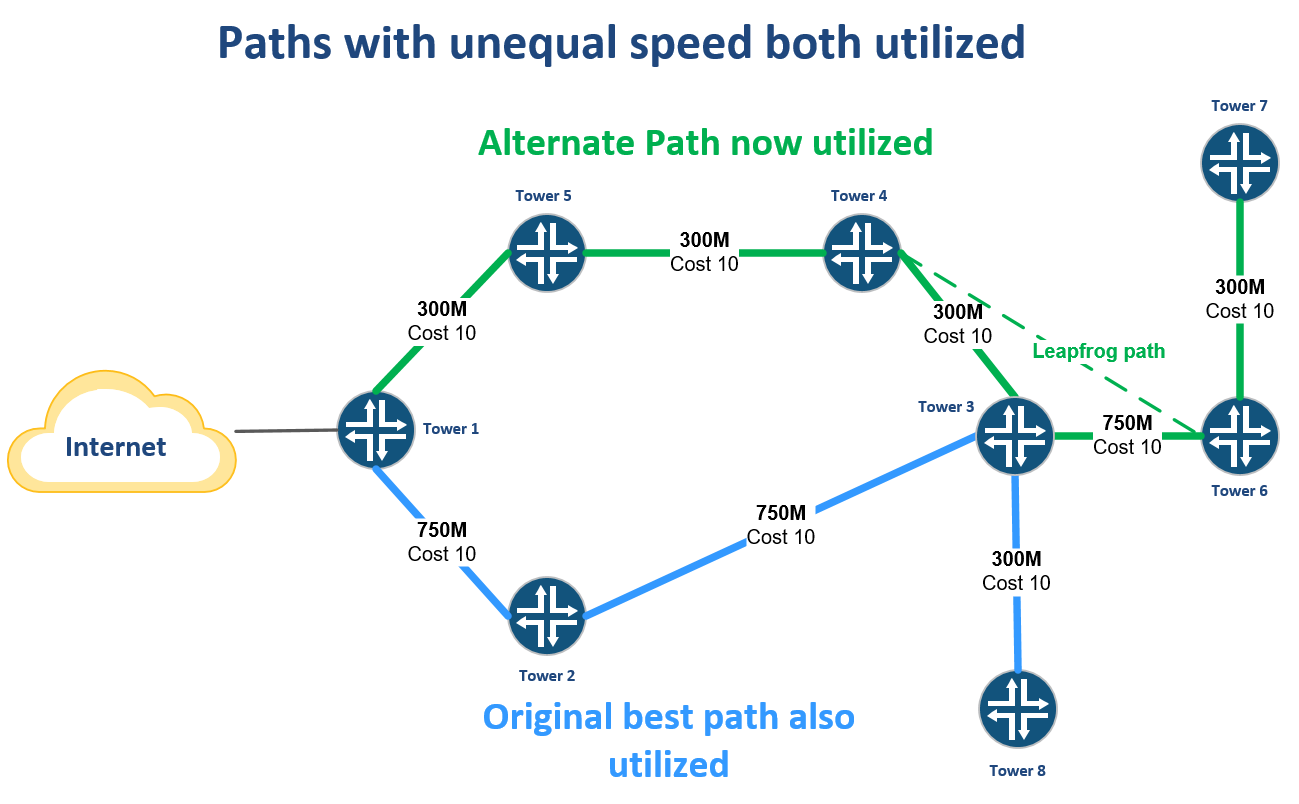
Tower 6 and 7 can now use the alternative path
Now that a lower cost path exists at Layer 3 for Tower 6 and 7, the original best path become less congested and bandwidth that was previously unused can now be used to load balance traffic.
How to build the new path?
I often recommend “switch-centric” architecture also known as “router-on-a-stick” when building a WISP – there are a number of benefits to doing this. In this case, since the switches handle all connections, it’s fairly easy to tag a VLAN from Tower 6 to Tower 4 and create the “leapfrog” path.
A few closing thoughts
This works well when the towers you need to move onto an alternate path are part of a stub network – that is, they only have one way into the aggregation point before the traffic is split.
If you were trying to do this with rings that connect to other rings and had redundant paths, there could be unintended results so you need to plan the costs and paths carefully.
Labbing the topology to see what will happen is always a good idea.
Hope this is helpful for someone looking to get just a little more bandwidth out of an OSPF based WISP network.
